1
\$\begingroup\$

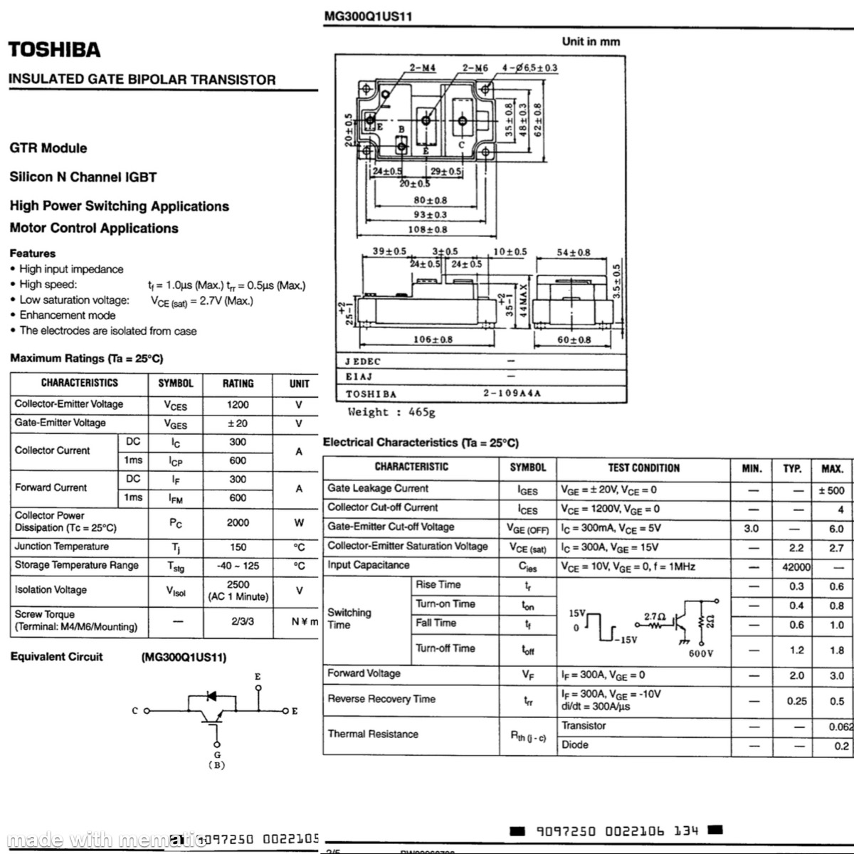
I have the IGBT above with no driver because I thought I could control with arduino, relay, and separate power supply.

I bought this device from eBay and it doesn’t turn off so Im not sure if it’s toast or not either, but assume the best.

I need help selecting a simple driver and help with wiring because I’m pretty much a novice with electronics(built a few devices with arduinos).

FYI I just need the IGBT switch to turn on a high voltage load for 0.2 second every few minutes. I want to control the IGBT/driver with my ardunio.

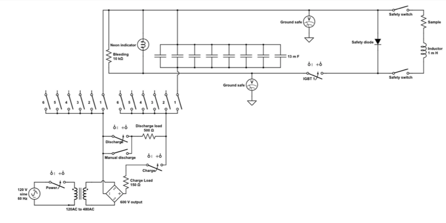
Below is a variation of the device. Mine has a 240-400 DC voltage coming from its ~60 mF capacitor bank. I'm trying to drive the current through a sample. My version doesnt have the inductor next to the sample.

The purpose of the device is to dump the electricity into a sample (on the right of the schematic). Here is a video describing the power system but I'm using an IGBT instead of the SCR. Go to mark 28:47 Youtube

enter image description here

enter image description here

\$\endgroup\$
13
  • \$\begingroup\$ We need a little more description of what you are trying to do and how you are trying to do it. A schematic would be good. But if you are talking high voltage AC, you have the wrong device. \$\endgroup\$ Commented Apr 18, 2023 at 22:43
  • \$\begingroup\$ How did you test it to conclude it doesn't turn off. We need pictures, schematics, and the intended purpose of the IGBT to be able to fully help you. \$\endgroup\$ Commented Apr 18, 2023 at 23:09
  • \$\begingroup\$ @Chauncy please delete that last comment ... add the info to your question ... this site is not a forum, where you keep adding info in comments \$\endgroup\$
    – jsotola
    Commented Apr 19, 2023 at 0:22
  • \$\begingroup\$ @JohnBirckhead I added the schematic. It is DC power. \$\endgroup\$
    – Chauncy
    Commented Apr 19, 2023 at 0:42
  • 1
    \$\begingroup\$ @Chauncy if you once connect a voltage between gate and emitter or accidentially touch the gate with a finger, this voltage remains inside the IGBT for hours or even days. The transistor is conducting all this time. To remove this voltage, you connect gate and emitter with a wire or resistor. If it is still conducting, it is dead. \$\endgroup\$
    – Jens
    Commented Apr 19, 2023 at 18:51

1 Answer 1

0
\$\begingroup\$

Here are some answers to your problem:

  1. While IGBT and SCR have similar on-state or saturation voltage drops across them while conducting, and similar turn-on times, their turn-on mechanisms are different; an SCR would require lower voltage and less current to turn on at the same speed as an IGBT, and while IGBT is controlled by gate-emitter voltage and only stays on while that voltage is sufficient, SCR simply needs a quick gate current pulse to trigger it and then it very quickly (in about 2 us) becomes fully self-conducting and remains on until its main channel current drops below a threshold.
    Conclusion: it's easier to turn an SCR on than an IGBT.

  2. While your IGBT has DC (constant and continuous) current rating of 300A, its pulse rating is ONLY TWICE as high, or 600A.
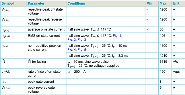
    An SCR rated for some continuous/average current can have peak current rating that is typically 10, 15 or even more times higher than its average rating.
    Here is a relevant part of BT158W SCR datasheet, for example: enter image description here While rated for 80A continuous average and 126A for RMS or DC current, its peak current rating is 1100A or 1200A.

  3. The video mentions 40uF total capacitance which at his recommended voltage of 237V gives a 1000A pulse!!!
    YOU actually have 50% higher capacitance, which means you will get a current pulse of about 1500A on discharge.
    THAT is the reason your IGBT is burned, or actually FUSED; its peak current rating is 2.5 times lower than the peak current it was exposed to.
    Even if you had used the recommended 40mF capacitance, a 1000A pulse would have destroyed your IGBT.
    You must use an SCR, and its peak rating has to be significantly higher than your expected peak current of about 1000A!
    I have checked Mouser and Digi-Key, and the SCRs rated above 1100-1200A pulse current very quickly become very expensive. One model that would work for you is Vishay's VS-ST110S08 or VS-ST110S12 (datasheet) or International Rectifier's ST110S08 or ST110S12 (datasheet); similar model numbers and characteristics, different manufacturers.

The lesson here is that you should use recommended values AND recommended types of devices, ESPECIALLY if you are a novice in electronics - specific component types and values are given for GOOD reasons.
I don't know why did you decide to go with higher capacitance and an IGBT instead of SCR as recommended, I understand you thought it would make it easier to control with Arduino, but you have actually made it worse because you don't have enough knowledge to make your own modifications to certain components or circuits.
But making mistakes is an active part of learning, and you actually learn and understand more from your mistakes than from everything going well because then you skip many important details.

Finally, this is a very serious, high voltage and high energy circuit which I recommend you always approach with caution and safety measures such as wearing rubber gloves like the man in the video.

\$\endgroup\$

Your Answer

By clicking “Post Your Answer”, you agree to our terms of service and acknowledge you have read our privacy policy.

Not the answer you're looking for? Browse other questions tagged or ask your own question.