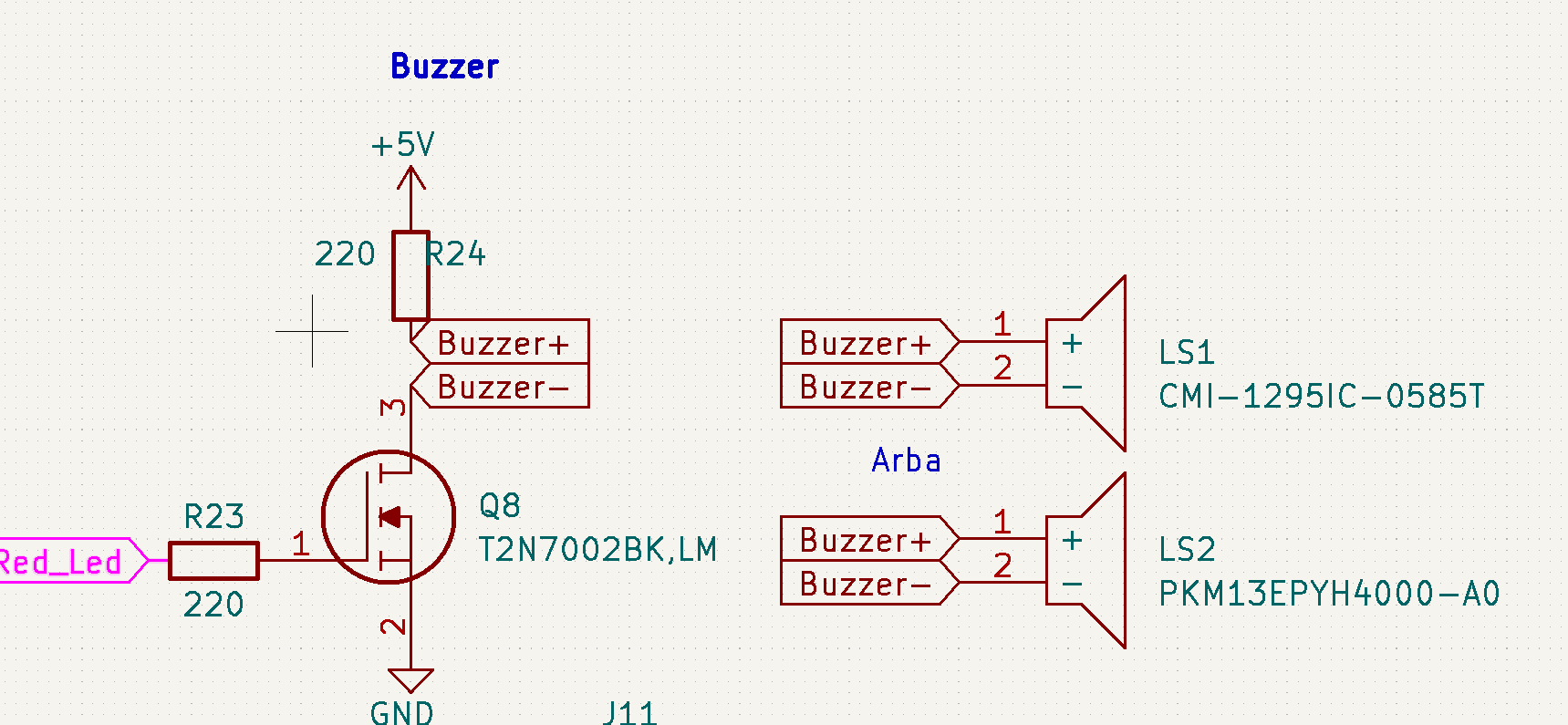
I just assembled my PCB design that uses an ESP32-c3-mini-1 as the brain.
I'm testing all the peripherals and found an error when testing buzzer circuit.
I'm using a T2N7002BK N-channel LM MOSFET as a switch to control 5V connected to a buzzer:
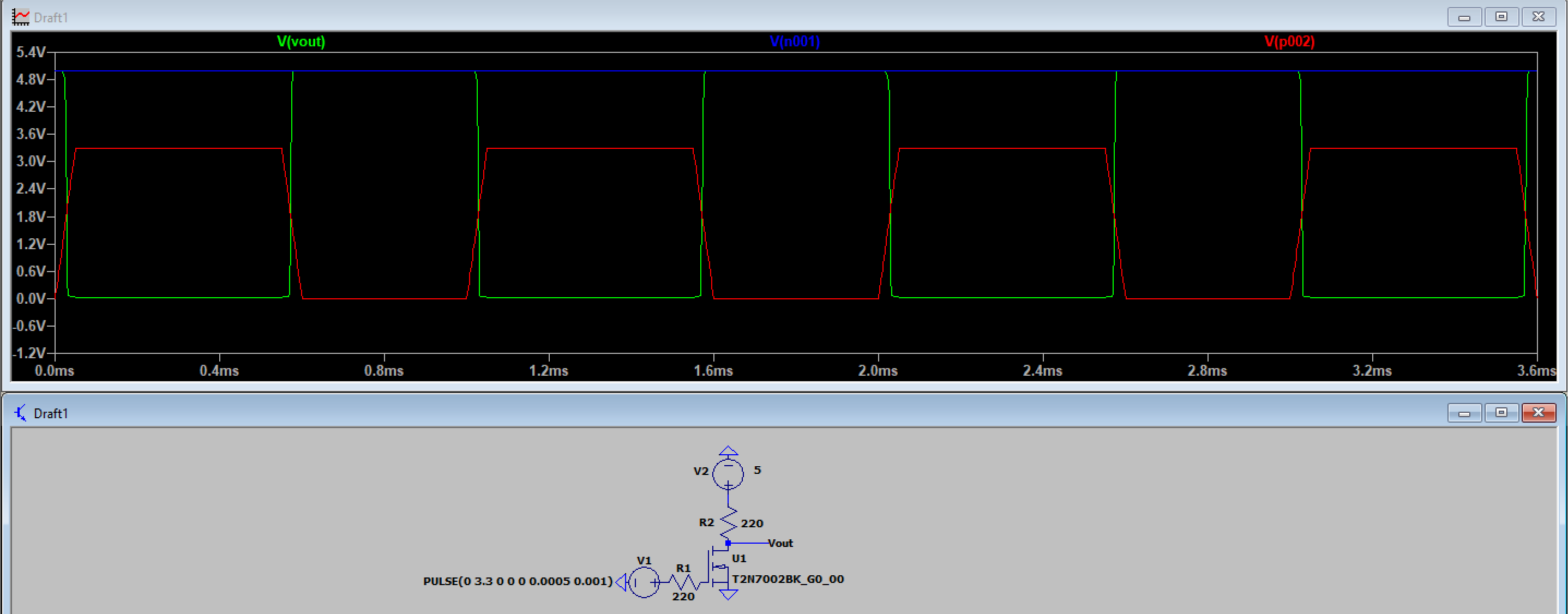
I am using only one buzzer. The MOSFET is controlled with the ESP32 using a 50% PWM signal with a frequency of 1kHz. I don't get any sound out of the buzzer. I used LTspice to simulate this schematic. Based on the simulation results, it should work:
This is the result I want to achieve, 5V pulse signal. I tested my PCB with an oscilloscope, everything seems to be fine until the MOSFET part. The 3.3V pulse signal is present on resistor R23, but the MOSFET does not open at all. When I short buzzer (placing my finger on contacts) it makes a super silent sound and I can see around 1V peak then a fast decay of a signal on the buzzer+ node.
Any ideas why my MOSFET is not working? Is it a faulty component, soldering error or schematic flaw?


