1
\$\begingroup\$

CAN Background

According to some places, CAN transceivers do not need GND connections since the line is differential. After long research and understanding how the CAN transceiver works, GND is essential. This is mainly because the transceiver generates the High/Low pulse with respect to its GND.

When BUS is not isolated, GND has the same reference as the input power.

Note that the CANBUS line and powerline might be long, therefore two non-isolated transceivers could have different GND references (the powerline acts as a resistor). To overcome this, there is a common-mode parameter on most CAN transceivers. The magnitude of the common mode is how much tolerance a CAN transceiver has with respect to its CAN GND.

Isolated DC to DC.

What happens when each device has isolated DC2DC, but does not have isolated CAN transceivers? Its GND reference is not the same as the other devices (with the same DC2DC), i.e. both have floating GND.

Questions:

  1. How does isolated DC2DC behave? What prevents the GND of device B and device A from being slightly different in magnitude?

  2. What is the most suitable way to connect the GND to ensure that the reference is the same? Otherwise nothing prevents the two devices to have very large GND difference and therefore to be be in the common-mode range.

  3. If a network has an ADM3053 (isolated) and a TCAN1044V-Q1 (non isolated), TCAN1042HGV-Q1, TJA1441 (non isolated) what is the best practice to connect all the GND references? Few devices have an isolated transceiver, few have isolated DC2DC, and some have neither, i.e are non-isolated.

EDIT

Theory

theoretically (A-G_1)-(B-G_1) = A-B. So the receiver does not need G1 and it can transmit with reference to G2. But this does not happen in practice. This is the common mode mention above and in other answers.

Connectivity

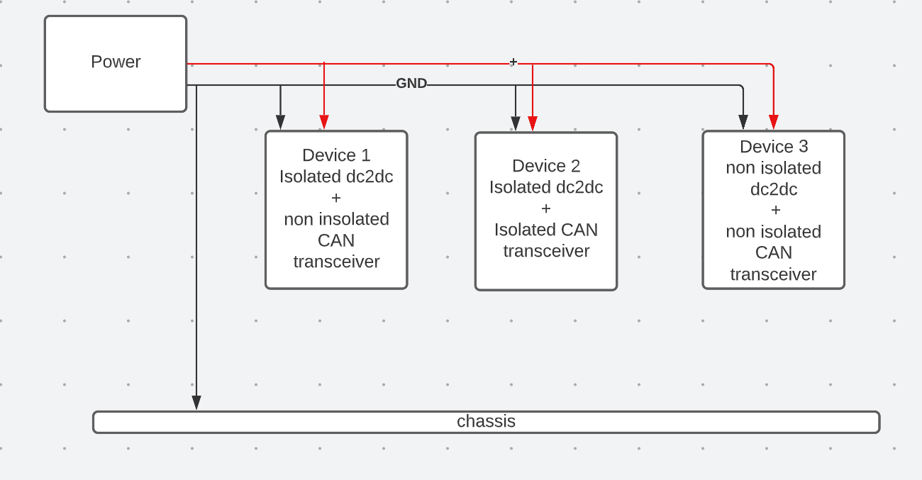
Given the following diagram: CAN Network

The CAN transceiver of those 3 devices does not share any common. device 1. has isolation in dc2dc level device 2. has isolation both in dc2dec level and in the transceiver level device 3. has reference to transceiver GND which is isolated. notice that chassis is reference to the power GND.

Connecting all CAN GND will work but it faces issues with ground loop and possibility of wrong current via ground. For example, if node 3 losses its GND connectivity of the power. Then the CAN GND becomes its GND and it might have a huge load via it.

\$\endgroup\$
3
  • \$\begingroup\$ All data communication requires a common ground/reference potential, not just CAN. That's how electricity works - voltages are always expressed in relation to something else. I always have a hard time understanding where these "doesn't need ground" myths come from. \$\endgroup\$
    – Lundin
    Commented May 2, 2023 at 14:32
  • \$\begingroup\$ A schematic or at least a block diagram would really help to make it clear what you're trying to do \$\endgroup\$
    – LordTeddy
    Commented May 3, 2023 at 21:31
  • \$\begingroup\$ @LordTeddy I added block diagram \$\endgroup\$
    – oak
    Commented May 11, 2023 at 14:14

3 Answers 3

1
\$\begingroup\$

Disclaimer: I'm answering your questions as I understand them. You will have to come back to me if I misunderstood you. First some background:

  1. Differential signaling and ground reference

In differential signaling, the signal is not referenced to ground, so in theory you don't need a ground connection between transmitter and receiver. However, you need a way to ensure that the receiver's common mode voltage range is not being violated. Since the common mode voltage on the receiver side is measured with respect to the receiver's own ground, this amounts to controlling/limiting the voltage difference between the transmitter's ground and the receiver's ground. It is not necessary to connect them directly, but there needs to be some sort of arrangement that limits the voltage difference in practice. The simplest such arrangement, of course, would be an explicit ground connection. This could be a metallic shield in the CAN cable.

Note that even with isolation, this situation isn't different in principle. However, the common mode voltage range is usually orders of magnitude greater than without isolation.

  1. Isolated CAN transceivers

Note that isolated CAN transceivers don't have the isolation barrier directly at the cable. There is some amount of electronics on the cable side (the actual transceiver), and this must be supplied with power. For this transceiver, the discussion above applies unchanged. The transceiver has its own ground, and its common mode voltage limits with respect to this ground.

The isolated CAN transceiver includes another chunk of electronics on the other side of the isolation barrier, and this part has its own ground. Its voltage can differ from the transceiver's ground by a substantial amount.

Your example of the ADM3053 also includes an isolated DC/DC converter to supply the transceiver with power. This allows you to have the electronics of your CAN node work from an arbitrary power source with its own ground level, but you still need to treat the transceiver ground (called GND2 in the ADM3053) in the same way as described above in 1.

  1. Floating ground

There is no such thing as a floating ground. In fact, there is no such thing as ground. There are only different signals we call "ground" (often somewhat arbitrarily), but this doesn't change their physical nature. A floating ground typically means that there is a signal we call "ground", which is coupled to another signal that we also call "ground", through a fairly high impedance (often this is predominantly capacitive).

In the context of a differential CAN bus, you invariably have - at least conceptually - a ground signal the bus is referenced to. It might be a chassis or metal structure everything is mounted on or in. It might be the cable shield. Regardless of whether you use non-isolated or isolated transceivers, you need to ensure that their common mode voltage restrictions are obeyed with respect to this ground signal. As the bus is differential, some amount of ground level variation is tolerable between the different points on this distributed ground structure, without impairing the communication.

  1. Isolated nodes

If you want to connect a node to the CAN bus, whose own ground can not be guaranteed to obey the rules laid out above, you need an isolated transceiver, which permits you to keep the ground for the node separate from the ground for the bus. This doesn't change the situation for the bus, but it does change the situation for the node. The node itself now has to deal with two different grounds, with potentially a large voltage between them. That's what the isolated transceivers are made to help with.


With this background, let me try to answer your 3 questions:

  1. "How does isolated DC2DC behave? What prevents the GND of device B and device A from being slightly different in magnitude?"

You need to be clear here which ground you mean. I assume you mean the ground of the node in question, and not the bus ground.

Due to the fact that you have an isolated transceiver, which also includes an isolated DC/DC converter to supply the transceiver circuit, you have three different grounds, which can all have a substantial voltage difference between them: The ground of node A, the ground of node B and the bus ground. Nothing prevents them to float against each other, and no problem results from this, as long as the breakdown voltage limits of the isolation barriers are respected.

  1. "What is the most suitable way to connect the GND to ensure that the reference is the same? Otherwise nothing prevents the two devices to have very large GND difference and therefore to be be in the common-mode range."

This depends on your concrete situation. In a car, for example, it will usually be adequate to use the car's chassis as the ground connection for the bus. The ground of all transceivers, isolated or not, should be connected to it. In isolated transceivers, however, the node ground (GND1 of the ADM3053) would typically not be connected to that.

In another situation, you may want to use a shielded bus cable, and use the shield as the bus ground connection.

  1. "If a network has an ADM3053 (isolated) and a TCAN1044V-Q1 (non isolated), TCAN1042HGV-Q1, TJA1441 (non isolated) what is the best practice to connect all the GND references? Few devices have an isolated transceiver, few have isolated DC2DC, and some have neither, i.e are non-isolated."

It again depends on the situation, similar to the previous question. The rule is that the grounds of the transceivers get connected to bus ground in one way or another. If the local ground of a node can't be connected to that, you need to use an isolated transceiver, in the way described above. If the transceiver doesn't include a DC/DC converter, you need to worry where the power for the actual transceiver circuit is coming from. Perhaps your bus cabling includes a wire for supplying power to the transceivers. In that case you can use this, instead of needing an isolated DC/DC converter.

TLDR; Connect all transceiver grounds to "bus ground". When necessary, keep a node's ground separate from that, through the usage of an isolated transceiver. But in general, be conscious of the different grounds, their function/purpose, and the currents flowing in them, even in case of a fault.

\$\endgroup\$
1
  • \$\begingroup\$ Hey @sh, thanks, I updated my question. I'm concern about ground loop and wrong flow of current \$\endgroup\$
    – oak
    Commented May 11, 2023 at 14:15
1
\$\begingroup\$

If you are using CAN-bus without can-gnd you are implying ground. For example, every ECU in a car eventually wires back to the battery and shares this ground.

Now, what if you cannot imply this common-ground? For example in industrial equipment where each node is powered from a different AC source or SMPS, of maybe even an entire asynchronous grid?
You will have to ensure can-gnd is wired to each tranceiver to maintain proper common mode at the tranciever. However as you can imaging this may cause ground loops and other noise hell. Or it may not even be technically or legally feasable. For noise/hum examples, just ask the audiophiles.

This is the reason isolated CAN-bus tranceivers are required. The entire electrical part of the CAN-node is only the tranceiver with 3 wires, CAN-H, CAN-L and CAN-GND.
The same applies to RS-485.

Pure balanced differential, with transformers and Manchester coding avoids this. Ethernet uses this approach. Each end of the ethernet transceiver goes through isolation transformers ensuring ground loops or other difficulties would never cause trouble. Here you can safely run just two wires.

If you are running an isolated CAN-bus the best case would be to wire the shield to chassis and the CAN-gnd to actual ground at one place. They sell special cable for this, eg: Phoenix Contact SAC-5P-920...

\$\endgroup\$
1
\$\begingroup\$

How does isolated DC2DC behave? What prevents the GND of device B and device A from being slightly different in magnitude?

It doesn't, that's kind of the point of isolating them. The GND potential on either side of an isolated DC-DC converter can be different by kV's. Often this is achieved using a transformer. The converter drives current through the primary side of the transformer, that is then smoothed on the secondary side to produce a given voltage, but isolated from the input.

What is the most suitable way to connect the GND to ensure that the reference is the same? Otherwise nothing prevents the two devices to have very large GND difference and therefore to be be in the common-mode range.

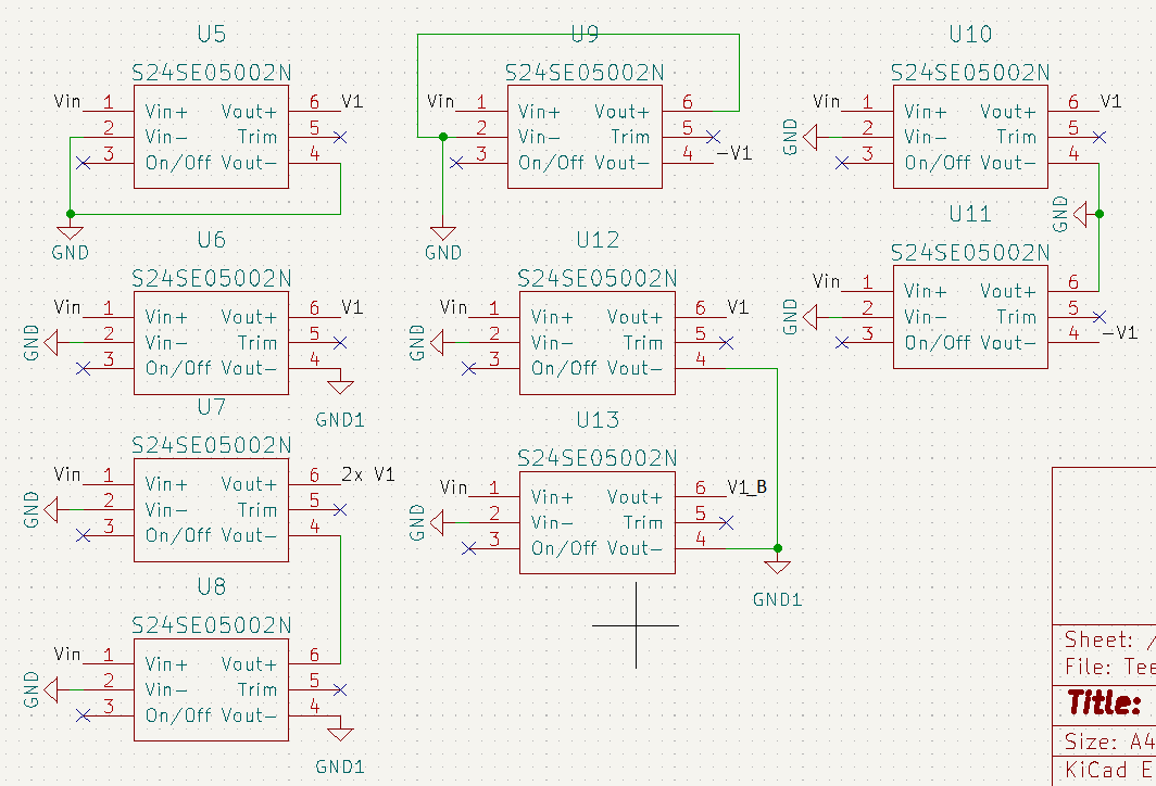
It's a bit unclear as to which GNDs you're talking about, but is also doesn't matter. You can connect the negative terminals of the input and output of an isolated DC-DC converter together if you want. You lose the isolation, but nothing bad happens. You can also connect the negative terminals of the isolated outputs of two DC-DC converters together, that's fine. You can even connect the positive terminal of one to the negative of another, to give you a bigger output voltage. That's also fine.enter image description here
All of the above are fine ways to connect isolated DC-DC converters (but not all at once!). Some maintain the isolation, some don't.

If a network has an ADM3053 (isolated) and a TCAN1044V-Q1 (non isolated), TCAN1042HGV-Q1, TJA1441 (non isolated) what is the best practice connecting all the GND references? Few devices have an isolated transceiver, few have isolated DC2DC, and some have neither, i.e are non-isolated.

At this point, I'm having to guess because your question lacks detail, but you could just connect all the GNDs together if you don't need the isolation. You'll need to connect all the GNDs associated with the CAN bus together at least, what you do with the isolation depends on your controllers, and what isolation you need.

Addressing your edit
If this is all inside one Chassis, then I don't see the need for these isolated CAN transceivers, though this might not be something you can change.

Connecting all CAN GND will work but it faces issues with ground loop and possibility of wrong current via ground.

A GND loop is only going to form if you wire your grounds in a loop, but you can control this and wire something differently (assuming this is a problem, which it isn't always). You might, for example, daisy chain your CAN bus with power and GND, from one device to an other. This removes the ground loop, but you have to make sure your cabling is thick enough to carry the required current.

For example, if node 3 losses its GND connectivity of the power. Then the CAN GND becomes its GND and it might have a huge load via it.

CAN GND and power GND should be the same thing, I don't see why you'd need to separate them. If they are the same adding, the second, low-current GND connection is unlikely to add any benefit. If you're planning on routing the GND using the chassis, then you don't need to also run a GND cable.

\$\endgroup\$
3
  • \$\begingroup\$ Hey @LordTeddy,thanks, I updated my question \$\endgroup\$
    – oak
    Commented May 11, 2023 at 14:15
  • \$\begingroup\$ @oak, I've added to my answer \$\endgroup\$
    – LordTeddy
    Commented May 15, 2023 at 17:18
  • \$\begingroup\$ Hey @LordTeddy, thanks. The reason is that we do not control the dc2dc isolation. somedevices have it. Nor, we do not control the can transceiver as well. So we have some devices isolation on the power level and some device on the transceiver as well. \$\endgroup\$
    – oak
    Commented May 22, 2023 at 14:57

Your Answer

By clicking “Post Your Answer”, you agree to our terms of service and acknowledge you have read our privacy policy.

Not the answer you're looking for? Browse other questions tagged or ask your own question.