0
\$\begingroup\$

I have a question about how to control this simple LED circuit that is being driven by a battery. I am not using a microcontroller in the set up so the control will have to be something else. The conditions are that sometimes the D1 LED can be shorted (from an external condition) so that the only load will be R1. I would like to be able to detect when D1 is shorted and shut down the circuit and then reenable the circuit when the short is cleared.

I was thinking of using a comparator to sense the voltage between R1 and D1 to make sure it is the forward voltage of D1 but that wont work because when the mosfet turns off this just floats to Vbatt and you couldnt detect the short to know when to turn it back on. Im trying to come up with a simple solution because this seems easy but Im stuck. There is a control signal I will use out of another circuit but it isnt a microcontroller so I was thinking of using an and gate with some other logic signal to detect the presence of a short across D1. The LED has a Vth of about 2.7V. If you think there is an easier way to drive this LED thats helpful too, maybe using the nFET isnt the best way.

Thanks for your help
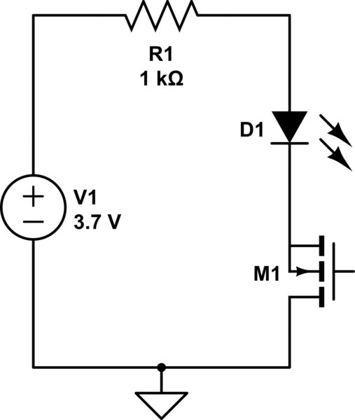
schematic

simulate this circuit – Schematic created using CircuitLab

\$\endgroup\$
7
  • \$\begingroup\$ Welcome! A PTC fuse? An e-fuse? \$\endgroup\$
    – winny
    Commented May 23, 2023 at 18:26
  • \$\begingroup\$ Thanks for the welcome! The problem is that when D1 is shorted the increase in current is only a few milliamps. Also how would you know when to reset the fuse? \$\endgroup\$
    – michael
    Commented May 23, 2023 at 18:34
  • \$\begingroup\$ Maybe I am missing something. What do you mean that D1 is shorted? That it fails in a short? That something external shorts it out? Do you mean when D1 is conducting normally because the transistor is on? \$\endgroup\$ Commented May 23, 2023 at 18:39
  • \$\begingroup\$ Sorry I should have been more clear about that. Yes, D1 can be shorted by an external condition. \$\endgroup\$
    – michael
    Commented May 23, 2023 at 18:50
  • \$\begingroup\$ You don’t, it resets itself when the short is removed. \$\endgroup\$
    – winny
    Commented May 23, 2023 at 19:23

2 Answers 2

0
\$\begingroup\$

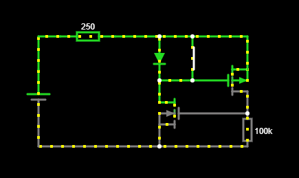
You might be able to do this with just MOSFETs, see the below image. Circuit
You can play with this circuit here
In this circuit, I'm using the switch as a stand-in for the short.
Under normal conditions, the forward voltage across the diode is used to create a negative VGS for the P-channel MOSFET, opening it. This, in turn, creates a positive voltage for the VGS of the n-channel, opening that.
When the short happens, it also shorts VGS, causing it to close.

I say might, because you need all your values to line up nicely for this circuit to work. You for starters need the forward voltage of the diode to be more than the VGS of the p-channel MOSFET.
You also need the circuit to be able to start. Which I'm not actually 100% on. You need the leakage through the n-channel, to create enough forward voltage of the diode to start opening the p-channel, to in turn open the n-channel fully. If things didn't line up well, you could get a circuit that doesn't start at all. There might actually be a way to do something similar with BJTs in a more reliable fashion.

\$\endgroup\$
3
  • \$\begingroup\$ this is def a clever way to turn off the circuit and so close to what I’m looking for, it just seems like once the pFET shuts down the circuit it doesn’t get started again once the short clears. I guess what you’re saying is that if the leakage is enough through the n-channel it might be enough to start it and it would kind of snowball into starting again? I guess I could call it a ‘soft start’ feature lol. Thanks for the help though I will keep thinking about this \$\endgroup\$
    – michael
    Commented May 24, 2023 at 1:32
  • \$\begingroup\$ I just realized that when I change the threshold voltage on the pFET to -1.5 (it says -1.5m at first on mine) and the resistor value to 1k, the circuit seems to start and stop perfectly! Do you think this seems reasonable? Thank you so much! \$\endgroup\$
    – michael
    Commented May 24, 2023 at 20:37
  • \$\begingroup\$ Getting parts whose values line up nicely is part of the challenge, it should work in theory though. 1k Ohm for the resistor across the gate of the nFET might waste a bit more power than necessary, hence why I've used a 100k. \$\endgroup\$
    – LordTeddy
    Commented May 30, 2023 at 10:34
1
\$\begingroup\$

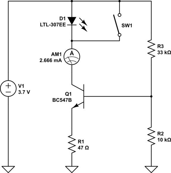
This constant current circuit provides nearly the same collector current with open and closed switch. This way the shorted LED will not be detected, but it has no impact on the rest of the circuit except more power loss in the transistor. This may be important if your circuit feeds a power LED.

The value of R1 defines the current as long as the base voltage is above, say, 0.8 V. The regulation is better and less temperature dependent at higher base voltages.

If you replace R2 by two diodes in series, the current is less dependent on the supply voltage.

schematic

simulate this circuit – Schematic created using CircuitLab
\$\endgroup\$

Your Answer

By clicking “Post Your Answer”, you agree to our terms of service and acknowledge you have read our privacy policy.

Not the answer you're looking for? Browse other questions tagged or ask your own question.