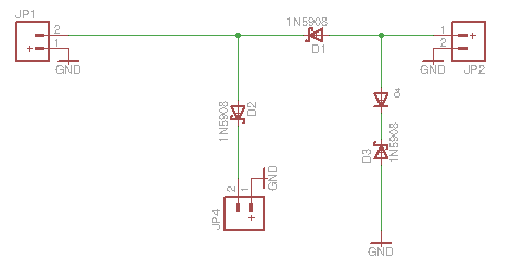
My electric fence unit stopped working, but it is a nice case with integrated solar panel and battery holder. I figured I could repurpose it as a rechargeable general purpose 6 V power supply. The solar panel still works fine and I think the battery does (although I let it run down flat so maybe not). I pulled the printed circuit and tried to figure out what bit actually charged the battery as opposed to doing the electric fence stuff. I came up with this circuit:

JP1 is the battery, JP2 is the solar panel. There are three Zener diodes as shown, all 1N5908 through hole parts and one SMD part which looks like a diode labelled M7 which, I gather, is a 1N4007 diode. I've put all this together on a PCB but I haven't grasped how it should work, and I'm not sure it does. When I tried it I did get some charge on the battery (got up to 2 V) but it discharged. I read up on Zener diodes 'cos I had only used ordinary ones before, and these seem to allow current through if the reverse voltage gets past 6 V. My solar panel goes up to 9 V max, that's what I've measured in full sun. I gather the battery (6 V SLA) likes about 6-7 V to charge. So I think that if the solar panel gets above 6v the D3 diode will send it to ground. But what I don't see is a way to cut off the charge when the battery is full. So three questions:
- Is this circuit likely to work or have I misinterpreted what I found?
- Is there something there that is cutting off the charge to the battery when it is full?
- Why would it discharge? I thought D1 would prevent that. Nothing was connected on JP4.
Obviously I'm no expert, so I do appreciate any help. Thanks.
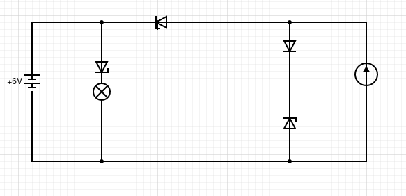
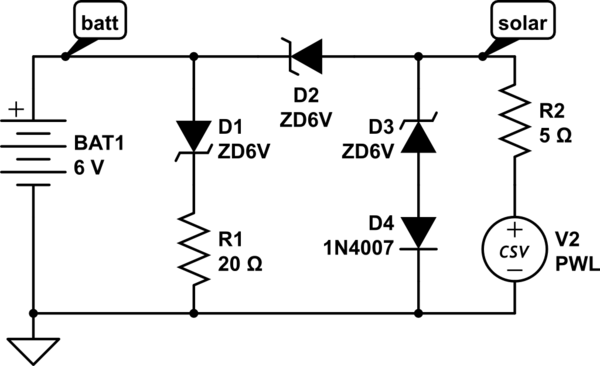
At @winny's suggestion I have redrawn the diagram

The battery is 6v as shown. There are three Zener diodes (1N5908) and one ordinary diode (1N4007). The solar panel, marked on the right as a current source is a 9v panel. I have shown the load as a lamp, but so far I have not connected a load to this circuit, and it won't be a lamp.


