1
\$\begingroup\$

Would someone care to explain why 10k resistors were chosen to be placed after the two LEDs near the CHRG and FAULT pins? I have looked at the documentation (linked below) and could not find an explanation for this. I have a very basic circuits understanding and the only logical conclusion I can come to is that they were chosen to not blow out the LED / to limit the current, but was confused why it was specifically 10k and not another value.

Is there any particular reason that 10k was chosen opposed to a different value? Is it just the most efficient at protecting the LED and the most common LED that fits that ohm range? Any help would be greatly appreciated, thank you.

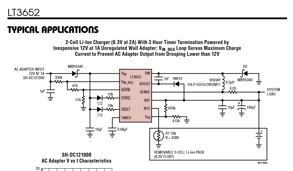
LT3652 Circuit

LT3652 Data Sheet

\$\endgroup\$
2
  • \$\begingroup\$ The datasheet you linked states that the CHRG and FAULT pins can sink up to 10mA, so it protects the chip as much as the LEDs. 10k is just a suggested value, make them lower if you want the LEDs brighter. \$\endgroup\$
    – Finbarr
    Commented May 31, 2023 at 20:52
  • \$\begingroup\$ look up a video or page describing "choosing a resistor of LED"; there's a lot of good explanations out there. \$\endgroup\$
    – dandavis
    Commented Jun 1, 2023 at 6:06

1 Answer 1

3
\$\begingroup\$

Those resistors limit the current through the LEDs to protect both the LEDs and the IC from excessive current.

10 K will limit the current to about 1 mA - I would probably try 3 to 5 K to make the LEDs a little brighter.

\$\endgroup\$
1
  • \$\begingroup\$ Thank you for the explanation Peter! That's what I was guessing the answer was but I was still unsure. Thank you for the clarification. \$\endgroup\$
    – John G.
    Commented Jun 2, 2023 at 13:48

Your Answer

By clicking “Post Your Answer”, you agree to our terms of service and acknowledge you have read our privacy policy.

Not the answer you're looking for? Browse other questions tagged or ask your own question.