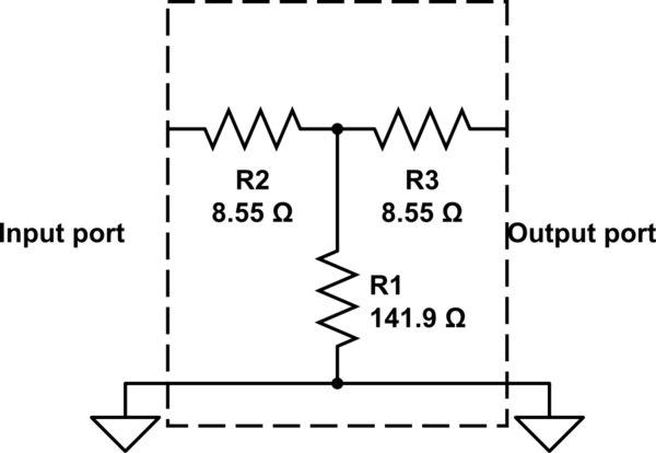
I had to measure and double check the exact impedance of my commercial 3dB attenuators, and I found out that even though my attenuator says it's 52.5 \$\Omega\$, I measured 150 \$\Omega\$ across input or output. Just to make sure that is not an error or a failed attenuator, I checked with an another 50 \$\Omega\$ attenuator and again ohmmeter read 150 \$\Omega\$. Could you please help me understand what am I doing wrong?
4 Answers
When we say an attenuator is "50 ohms" we mean that it has a 50-ohm input impedance. It is also assumed that the output is properly terminated when measuring the input impedance.
That means you should be connecting a 50-ohm load to the output of the attenuator, and then measuring the impedance between the center pin and ground at the input port.
Note that measuring at DC with an ohmmeter will give you a good idea of what the impedance is at low frequencies, but for RF use you may be more concerned with how the device performs at RF frequencies. To measure the RF input impedance, you typically use a network analyzer and measure the RF reflections (again, with the output port terminated), then calculate the input impedance from the reflection coefficient.
A 3dB attenuator for a 50-ohm system might be constructed in the "T" format:

simulate this circuit – Schematic created using CircuitLab
If you measure either input port or output port, should be 150.48 ohms. Try measuring resistance from input port's "hot" pin to output port's "hot" pin...should be near 17 ohms.
-
3\$\begingroup\$ And if you connect the output to a 50 Ω terminator, measuring the input port should give you approximately 50 Ω. \$\endgroup\$– HearthCommented Jun 14, 2023 at 1:10
-
\$\begingroup\$ @Hearth I had assumed that ohmmeter measurements were made to an isolated 3dB attenuator. I'd be cautious about using an ohmmeter to measure an attenuator connected to a cable terminated into another device. That other device could be AC-coupled via a series capacitor, or a bias-T, or a transformer. \$\endgroup\$ Commented Jun 16, 2023 at 13:39
-
\$\begingroup\$ Right, I'm just explaining to the asker that it's not called a 50 Ω attenuator for nothing. I feel like knowing that putting a 50 Ω resistor on the output and then measuring it does result in seeing 50 Ω on the input would help avoid confusion. And terminators are nearly always just resistors; I've never seen one that was AC-coupled. Another device that isn't just a terminator, sure, but that's why I specifically said a 50 Ω terminator. \$\endgroup\$– HearthCommented Jun 16, 2023 at 13:41
The 'impedance' of an attenuator is the input resistance it presents when the output is connected to the same value of resistance, the impedance of the system it's designed to be used in. Unfortunately if you wanted to measure an unknown attenuator using this definition directly, you would need to make iterated measurements and have a known resistance box.
A good trick I discovered (I'm sure others have discovered it but I've not seen it written up) to measure the design impedance of an attenuator with a DMM is to measure its input resistance with a) the output open, and b) the output shorted, and take the geometric mean. It works for any attenuation, and any arbitrary resistive network inside the attenuator, whether T, Pi, or connections onto a resistive film.
To take a worked example, using the values from glen_geek's answer for a T pad, Ropen = 150.45, Rsc = 16.614, and the square root of the product is 49.995, that's 50 to within the precision presented.
There are some attenuator design calculators on the net, try this with a few of their results for different configurations, impedances, attenuations.
You must take into account that the concept of resistance (R) only applies to DC pure resistive circuits. Impedance (Z) relates to AC circuits with capacitors, coils and maybe resistors. You cannot measure an attenuator (or the attenuation introduced by, for example, a splitter) using a pure DC signal, as the generated by a normal polimeter. In fact, impedance of a circuit varies depending on the frequency of the signal.
https://circuitglobe.com/difference-between-resistance-and-impedance.html
