1
\$\begingroup\$

I have recently made a High Z (1 MΩ) attenuator with R1= R3= 8.75 MΩ, and R2= 243 kΩ. I am using an LCR meter to test the impedance at higher frequencies. At frequencies above 50 kHz, the impedance is much smaller than the 1 MΩ intended value. I am using the mean sum method where Z= sqrt ((R of closed circuit) * (R of open circuit))

Keep in mind, the method I am using for calculating impedance is just a method of estimation. Moreover, I am an amateur; so please keep in mind obvious mistakes are not so obvious for me.
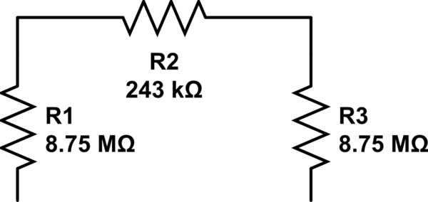
schematic

simulate this circuit – Schematic created using CircuitLab

\$\endgroup\$
2
  • 2
    \$\begingroup\$ Show us your PCB layout. \$\endgroup\$
    – Hearth
    Commented Oct 11, 2023 at 1:43
  • 4
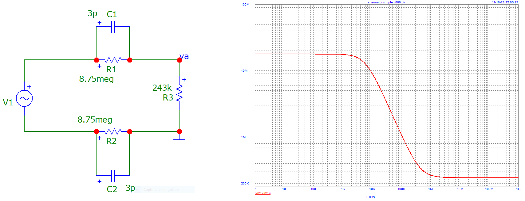
    \$\begingroup\$ The point is, at high frequencies and high resistances, even tiny parasitic capacitances become very significant. For example, at 50 kHz, just 3 pF of stray capacitance has an impedance of 1 megohm, which is low enough to affect your measurements. \$\endgroup\$
    – Dave Tweed
    Commented Oct 11, 2023 at 3:07

1 Answer 1

1
\$\begingroup\$

As pointed out by @DaveTweed, capacitors have some impedance ...

One can note the "evolution" of global impedance of attenuator.

enter image description here

\$\endgroup\$

Your Answer

By clicking “Post Your Answer”, you agree to our terms of service and acknowledge you have read our privacy policy.

Not the answer you're looking for? Browse other questions tagged or ask your own question.