1
\$\begingroup\$

I'm currently designing a IoT device based on an ESP32. This one comes on a mainboard where HAT could be plugged in (nothing new here).

The current HAT I'm working on is a temperature and humidity sensor board with either an HTU21 or HTU31D (the I2C version of the 2 ICs).

The overall PCB is working fine except for the measurements part (which is quite annoying for a temperature and humidity sensor). As soon as the MCU is warming up a bit, the HTU21 get all that heat and thus the measurement is not accurate at all (in regard of an old analog thermometer).

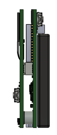
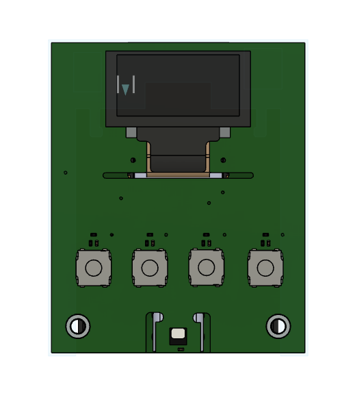
The 2 PCBs are mounted like so :

Top view of the full device

Side view of the full device

I followed up the design recommendation of the HTU21D by designing a notch around the sensor and removing any copper plane on the sensor island. The only thing that I did not remove is the thermal pad below it.

The PCBs have been manufactured using Aisler and are 1.6mm 4L PCB.

I'm currently planning to make a second batch of the PCB but in 0.8mm 4L PCB (but with JLC) but I would like to know if someone had advices about this and how I could avoid thermal influence of ESP.

I also think about moving the sensor on a separate PCB but I would like to keep the number of PCB as low as possible for the final assembly to reduce cost.

I'm building up this as a project for my company (I'm a freelancer as secondary job) and It supposed to be fully open source but I'm struggling a bit right now. (I should open a public repo for this I want the design to be fully fixed before doing so, I don't want people to have so issues while doing the same mistakes as me).

\$\endgroup\$

1 Answer 1

1
\$\begingroup\$

I had the same problem. Even if you use a separate board, as long as the sensor is in the same box, it will pick up the heat from the boards. What I did was use this cover for the sensor:

Temperature/Humidity waterproof cover

And installed the sensor out of the box. This helps to keep the sensor away from the heat of the board and it's in good contact with the environment's temperature and humidity. After putting the sensor in, I also had to seal the hole so the heat from the boards would not reach the sensor.

There is a narrow PCB available for HTU21D that fits this cover. This way, you don't need to design the external PCB yourself, and it fits perfectly to some of these covers. I can't remember the supplier I bought it from, but this one look very much like it:

SHT20 SHT21 SHT25 HTU21D SENSOR PCB

\$\endgroup\$
3
  • \$\begingroup\$ Hey Saadat, thank you for your answer. This kind of case could be very useful thank for the idea! Did you also tried with a thin PCB ? I saw in a TI document that thin PCB and even flex PCB could better for temperature sensors due to their lower thermal conductance (and I think flex PCB are in polyamide, so is the kapton tape I think) \$\endgroup\$ Commented Sep 1, 2023 at 16:09
  • \$\begingroup\$ I didn't use a flex, but it seems a better idea. I modified the answer and added the one that looks like the one I used. They also have the cover they designed the PCB for in that link. \$\endgroup\$
    – Saadat
    Commented Sep 4, 2023 at 7:36
  • \$\begingroup\$ Thanks again Saadat. I'll Try the flex and thin PCB also, to see if there is any différences and I'll also try an external sensor PCB. I'll post the result of my test on this question as soon as I've got my hands on them. \$\endgroup\$ Commented Sep 6, 2023 at 4:25

Your Answer

By clicking “Post Your Answer”, you agree to our terms of service and acknowledge you have read our privacy policy.

Not the answer you're looking for? Browse other questions tagged or ask your own question.