2
\$\begingroup\$

Currently, I am building a simple Z80 computer system on breadboard. I am at the point where I need to start learning how the display module works so that I can have some output. I cannot for the life of me get the display to show anything, no matter what bytes I send to it. Below is the ASM code I last used for testing. My Z80 is being run at 120 Hz for these tests. I have also tried many other initialization routines I have found online to no avail, but this one is based on the one specified in the ST7920's manual.

ld hl,initData  ;Memory location holding a string of bytes that are used for initialization
initLoop:
    ld a,(hl)   ;Load init byte at HL to A
    cp $ff
    jr z, breakLoop ;Break if the end of string is reached
    out $00,a       ;Send init byte to display's instruction register
    inc hl          ;Move to subsequent init byte
    jr initLoop
    
breakLoop:
ld hl,displayData

displayLoop:    ;Feed bytes from displayData into display RAM
    ld a,(hl)
    cp $ff
    jr z, breakLoop2
    out $01,a
    inc hl
    jr displayLoop
    
breakLoop2:
halt

initData:
    .db $30 ;Function set, 8-bit parallel, basic intstruction  \
    .db $30 ;Function set, 8-bit parallel, basic intstruction   |
    .db $0c ;Display ON, cursor and blink OFF                   |---Taken from manual
    .db $01 ;Display clear                                      |
    .db $06 ;Address counter auto-increment after read/write   /
    
    .db $34 ;Function set, 8-bit parallel, extended instruction
    .db $80 ;Graphic display address set y
    .db $80 ;Graphic display address set x
    .db $36 ;Graphic display ON
    .db $32 ;Basic instruction set
    .db $ff ;End loop
    
displayData:
    .db $21
    .db $21
    .db $21
    .db $21
    .db $21
    .db $21
    .db $ff ;End loop

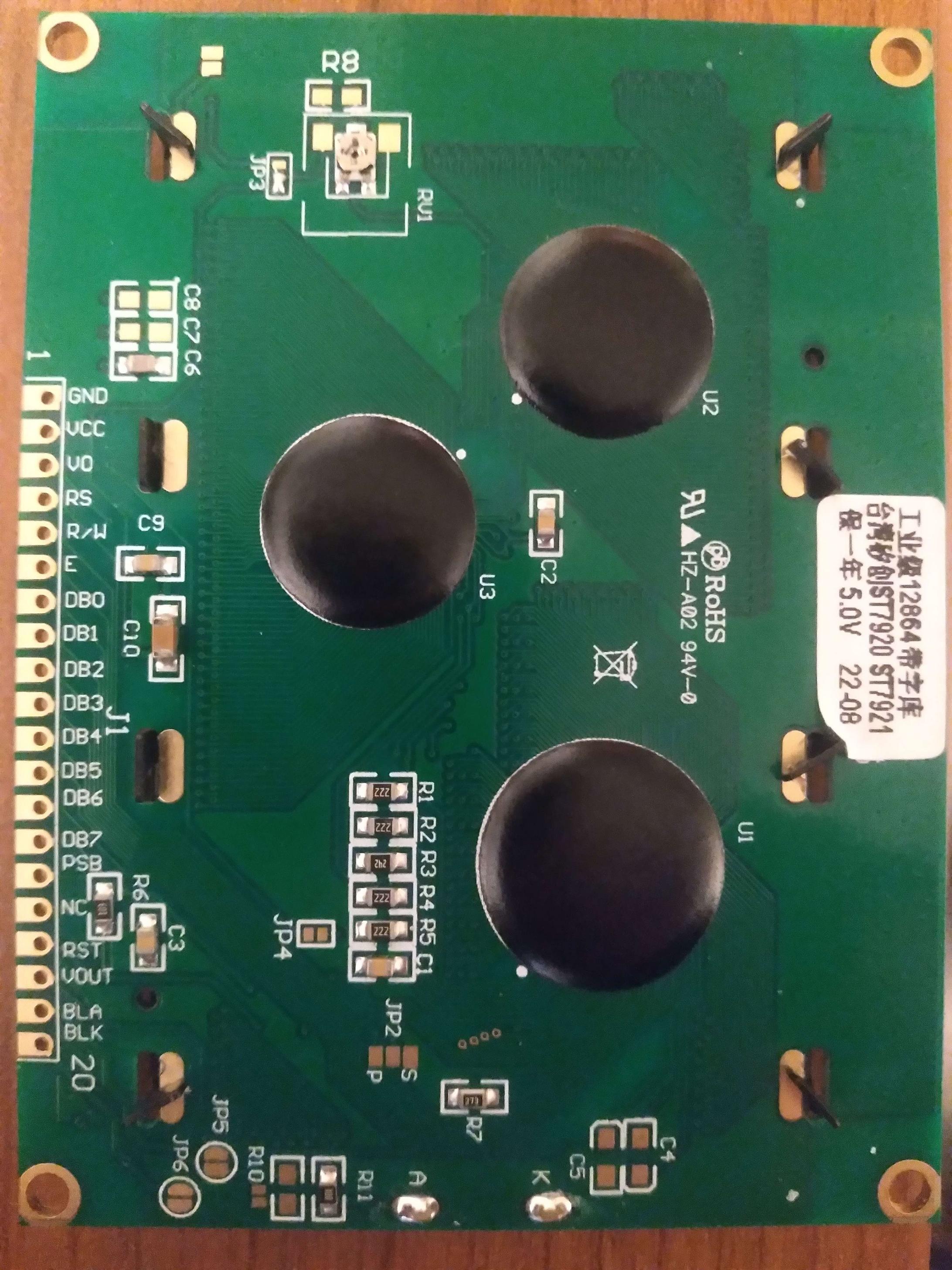
Note that sending to port 0 enables the display's instruction register, and port 1 allows display data I/O. I have verified that these signals and CE go low at the appropriate times, so I am almost inclined to believe that the issue falls on the bytes I am feeding the device. Every pin connection on the device has been tested, and I have done much research to make sure my connections are correct. Below, I will include a reduced schematic of my system showing only connections between the Z80 and display, and a picture of the display module's back side. displaySchematic XimimarkLCD
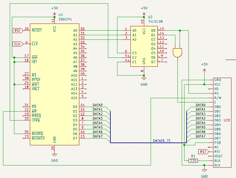
One strange thing that has occurred very rarely before is that running initialization will cause a blinking 16x16 cursor to show up in the middle of the screen, move once, and then disappear from the screen. This happened consistently with a certain string of bytes, but I have not been able to recreate it since, nor was it even what I wanted it to do in the first place. Another occurrence was the appearance of junk data all over the screen. I think this could be due to a bad reset signal. In any case, I'm hoping that somebody who has experience with these tricky devices can come up with a solution, or at least guide me in the right direction.

UPDATE 1: It was brought to my attention that the display's CE pin is active high, unlike the RST and WR pins. I performed a nand operation on the port 1 and 2 enable signals in order to generate the correct CE signal for the device. Previously, CE was equal to P1 & P2 I pulled all the wires for the display, and reconnected them 1 by 1 to ensure that my wiring was correct. I don't own an oscope, but I was able to manually clock my z80 system and observe the CE, WR, and RS signals before, during, and after a display operation. The signals seemed to match what is shown in the device manual, and I am still left with the same problem as before.

\$\endgroup\$
4
  • \$\begingroup\$ Welcome! Where are your decoupling capacitors? \$\endgroup\$
    – winny
    Commented Sep 26, 2023 at 9:07
  • \$\begingroup\$ I have a 100uf and 100nf capacitor on the power rail of the breadboard the device is mounted on. \$\endgroup\$ Commented Sep 26, 2023 at 13:43
  • 1
    \$\begingroup\$ I see. Best practice is to place them as close to each IC as possible. Just a hint to save yourself trouble on your future designs. \$\endgroup\$
    – winny
    Commented Sep 26, 2023 at 16:02
  • \$\begingroup\$ I’m pretty sure you own an oscilloscope - at 120Hz your PC’s sound card will give you two channels of scope. I’d also suggest that you get yourself a Salaea logic clone - probably the best $10 usd I’ve spent on test equipment. \$\endgroup\$
    – Kartman
    Commented Sep 27, 2023 at 13:07

3 Answers 3

2
\$\begingroup\$

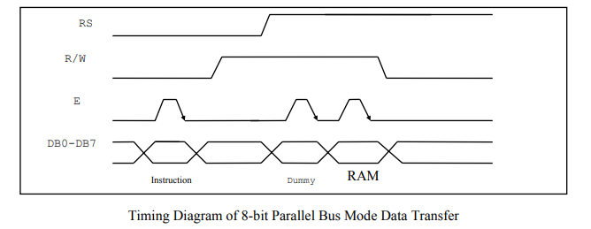
Are the signals good?
Did you verify these ...

enter image description here

\$\endgroup\$
4
  • \$\begingroup\$ I have verified the data, enable, R/W, and RS signals, although the latter 3 are opposite as the device is active low. \$\endgroup\$ Commented Sep 26, 2023 at 13:52
  • \$\begingroup\$ @5vComputerGuy "the latter 3 are opposite as the device is active low" what do you mean by this? I'd expect the signals to be exactly as shown in the datasheet. \$\endgroup\$
    – jonathanjo
    Commented Sep 26, 2023 at 15:21
  • \$\begingroup\$ @jonathanjo By "active low", I mean that the pin's function is enabled by asserting logic level 0. Both the write pin and reset pin are enabled by sending logic 0. However you are correct with the chip enable pin. I have now wired ports 1 and 2 enable lines to a nand gate, which then feeds into the display's E pin. I am still having the same issue as before. \$\endgroup\$ Commented Sep 26, 2023 at 19:11
  • \$\begingroup\$ @5vComputerGuy can you ensure your diagram matches your current circuit; it's hard for us to know what's changed. \$\endgroup\$
    – jonathanjo
    Commented Sep 26, 2023 at 20:37
2
\$\begingroup\$

I believe the display configured for serial interface but the code (and rest of circuit) is designed to drive it as 8-bit parallel.

This will need to be fixed, as well as checking for potentially other problems. An easy-to-read library to compare your code against is gordoste / pic32glcd at Github. It's not a good idea to leave the various inputs floating: /INT, /NMI, /WAIT, /BUSREQ.

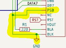
Your circuit diagram shows PSB connected to ground.

enter image description here

The datasheet says

enter image description here
From datasheet, p7.

\$\endgroup\$
2
  • \$\begingroup\$ I'm afraid I made a mistake when creating that circuit diagram. Right now on my breadboard PSB is fixed high, so that it is running in parallel mode. \$\endgroup\$ Commented Sep 26, 2023 at 13:42
  • \$\begingroup\$ My original question has been edited so as to include a more accurate diagram. Thank you for bringing this to my attention. \$\endgroup\$ Commented Sep 26, 2023 at 13:53
1
\$\begingroup\$

You may do better direct wiring A0 to RS, as you are changing RS at almost exactly the same time as your E signal , so the display is likely getting an indeterminate RS value. Check the setup time of RS to E in the display datasheet.

If you route A0 to RS, then it will be setup before IORQ goes low and the E signal activates from your address decoder plus NAND gate.

OMG its about 45 years ago I was doing this stuff on a Z80, skipping school sports afternoons to build hardware..

\$\endgroup\$
1
  • \$\begingroup\$ Tried connecting RS to A0, but my problem persists. I will keep it wired as you said for now, so I don't end up walking into that rake in the future. \$\endgroup\$ Commented Sep 27, 2023 at 3:18

Your Answer

By clicking “Post Your Answer”, you agree to our terms of service and acknowledge you have read our privacy policy.

Not the answer you're looking for? Browse other questions tagged or ask your own question.