0
\$\begingroup\$

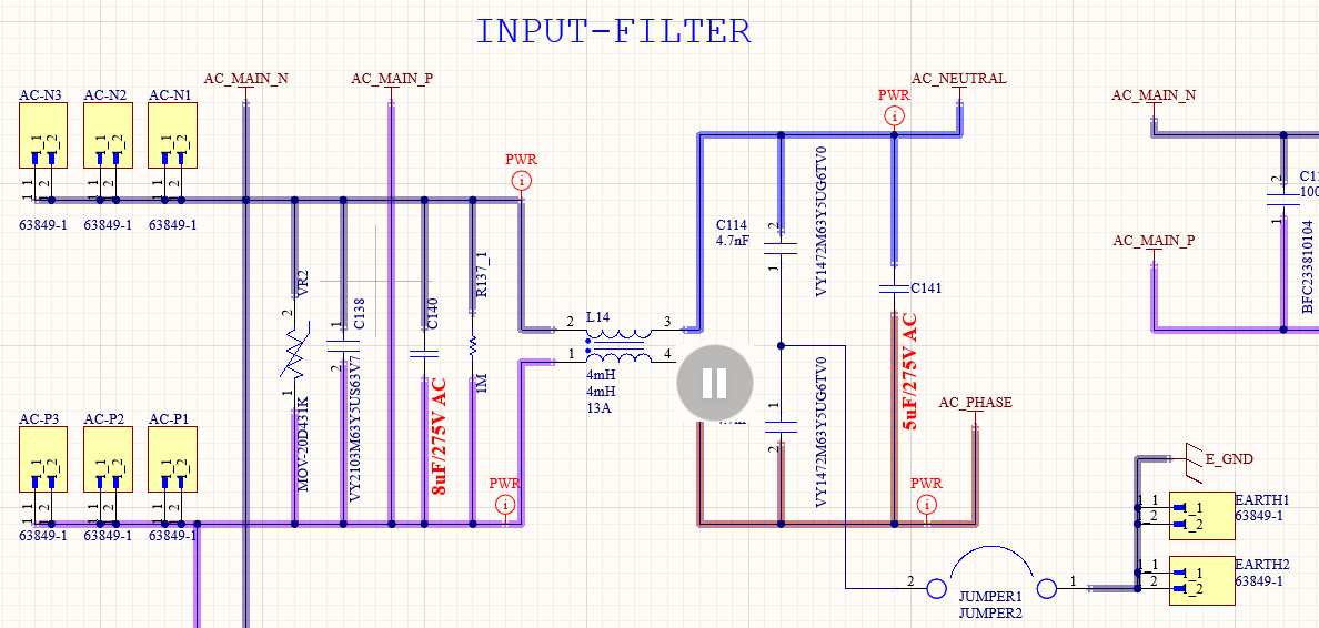
Our device is an induction cooktop rated for 2 kW of power. We have added an AC line filter in series with the AC supply line for EMI/EMC performance. Following is the circuit which we have implemented.

schematic

The issue that we are facing is: when the power is supplied to the filter circuit (even when it is not connected to the product's main PCB), the multimeter reads 1.4 A of current supplied through the line. The nets AC_NEUTRAL and AC_PHASE are not connected anywhere in this experiment. What is happening here? Is this something related to the power factor degradation? There is no component in the circuit getting heated. Any thoughts in the right direction are very much appreciated.

\$\endgroup\$
1
  • \$\begingroup\$ Current does not get consumed - energy(/power) does. \$\endgroup\$
    – greybeard
    Commented Oct 19, 2023 at 5:21

1 Answer 1

2
\$\begingroup\$

Well, let's do the math.

You've got 8.01 μF of capacitance before the common-mode choke (aside: are you sure a Y5U ceramic capacitor is safe to put across the AC lines? That sounds like a bad idea, it should probably be a class-X capacitor. And why are you using Y5U?), and 5.002 μF after it. Let's round off the smaller capacitors and just say we have 13 μF across the line. I'll also assume the common-mode choke is ideal and has zero differential-mode impedance.

I'll assume you're in a 50 Hz, 230 V country, because that makes the numbers work out to closer to what you're seeing. At 50 Hz, 13 μF has a reactance of -j245 Ω. With 230 V across the lines, that will consume a little under an amp of current. This is entirely reactive power, so nothing should get hot--you're just charging and discharging capacitors.

Considering that capacitors can vary quite a bit in their capacitance, 1.4 A isn't out of the realm of possibility if your capacitors are higher-than-nominal capacitance. I can also see at least one other capacitor connected across the lines in the screenshot you've shown, so there may be more as well. I also don't know what voltage or frequency you're using; I made a guess, but higher frequencies and higher voltages will increase the current.

The 1 MΩ resistor and the varistor won't affect things significantly, as they're both going to be much higher impedance than the capacitors.

\$\endgroup\$
2
  • \$\begingroup\$ Many thanks for the response Hearth. Regarding the Y5U cap, I'll recheck the part number and verify that there are not errors. understood the reason for consumption of 1A of current. Does this mean that we will have to design the filter using a lower value capacitances to reduce the overall reactive power being consumed in the system? Also, will it be okay if I can eliminate the 5uF cap altogether? \$\endgroup\$
    – Sarth Dave
    Commented Oct 18, 2023 at 13:25
  • \$\begingroup\$ @SarthDave I can't answer those questions for you, because it depends on your requirements. Any line filter is going to reduce your power factor. \$\endgroup\$
    – Hearth
    Commented Oct 18, 2023 at 13:37

Your Answer

By clicking “Post Your Answer”, you agree to our terms of service and acknowledge you have read our privacy policy.

Not the answer you're looking for? Browse other questions tagged or ask your own question.