1
\$\begingroup\$

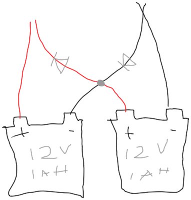
wiring diagram for two batteries in both series and parallel with diodes to prevent shooting

Can someone please explain to me what would happen here?

If you take two 12 V 1 Ah batteries and simultaneously connect them in series and parallel with diodes to prevent the shorts. At the ends you'd have both the equivalent of 12 V 2 Ah and 24 V 1 Ah from the same sources? There have to be notable issues with this, please help me understand what's going on.

(sorry for the terrible phone drawing)

Edit: assuming you were going to use the top left red as the positive and top right black as the negative for your power source. Yes, the red aren't actually touching in the picture, pretend that they are touching, please ignore my poor touch screen drawing abilities

\$\endgroup\$
3
  • 1
    \$\begingroup\$ All you have there is 2 batteries in series. The diodes do nothing because they're reverse-biased. \$\endgroup\$
    – brhans
    Commented Oct 20, 2023 at 4:12
  • 1
    \$\begingroup\$ Interresting fact, we can found this configuration in series solar panel. \$\endgroup\$
    – M lab
    Commented Oct 20, 2023 at 4:53
  • \$\begingroup\$ Can you please explain to me what you mean by short through the diodes? Why don't the diodes stop that from happening? \$\endgroup\$
    – biroshima
    Commented Oct 20, 2023 at 13:13

1 Answer 1

3
\$\begingroup\$

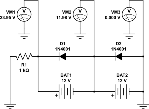
Another way to draw this same connection scheme is:

schematic

simulate this circuit – Schematic created using CircuitLab

The batteries are effectively connected in series, which creates a 24 V battery bank. The diodes are each then reverse-biased across each battery, which means they don't conduct.* Ultimately, you have a 24 V battery with the current capacity of one, or 24 V 1 Ah.

You should be able to easily see that they are not also in parallel. Another way to examine this is to see that the voltage at the node between the diodes is 12 V, but because the D1 cathode has a higher voltage than its anode, it isn't doing anything.

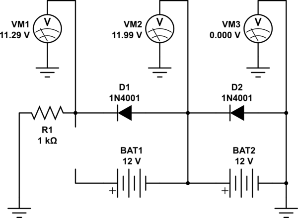
If you break the connection from BAT1 positive to D1, then you would get ~11.3 volts at R1. This is because the voltage at the anode is now greater than the voltage at the cathode, and the diode itself has a voltage drop of 600-700 mV. However that puts D1 in series with the load, which means the voltage is dropped by the diode and the diode has to be able to handle the load current.

schematic

simulate this circuit

* Ignoring leakage current.

\$\endgroup\$

Your Answer

By clicking “Post Your Answer”, you agree to our terms of service and acknowledge you have read our privacy policy.

Not the answer you're looking for? Browse other questions tagged or ask your own question.