0
\$\begingroup\$

I know the formula to calculate the constant time for capacitor is t=RC and for full charge t=5RC.

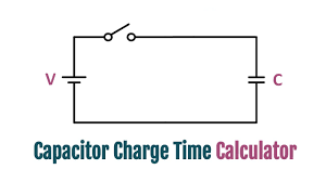
In the following example there is not resistor in the circuit but of course we are not in the ideal world so the internal resistor of the battery is added as series resistor with the capacitor.

enter image description here

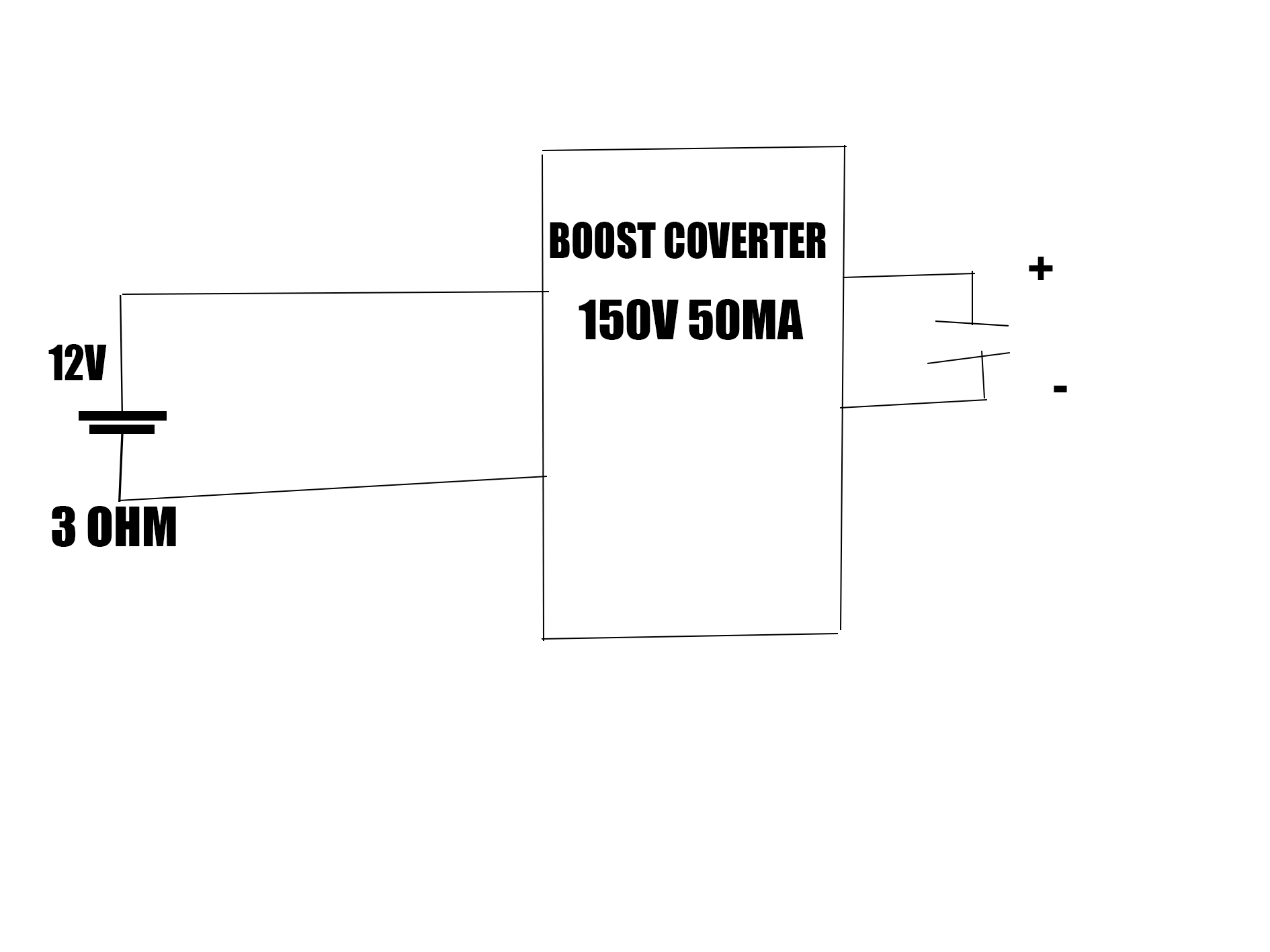
But if we connect the battery to a boost converter to charge the capacitor, let’s say:

  • capacitor is 1000 uF, 150 V
  • boost converter output is 150 V, 50 mA 6 Ω (I do not know how to read the boost converter resistance should i just measure the resistance between it's output terminals)
  • battery 12 V 3 Ω

How we calculate the constant time here? Which resistor (internal battery resistor or the boost converter resistor or both) will be used to calculate the constant time?

enter image description here

\$\endgroup\$
7
  • 1
    \$\begingroup\$ Whatever impedance you measured between the output terminals is meaningless. This is going to depend on the characteristics of the boost converter that you haven't shown--soft-start features, overcurrent features, that sort of stuff. \$\endgroup\$
    – Hearth
    Commented Oct 24, 2023 at 11:45
  • 1
    \$\begingroup\$ For raw estimation of charging time you can use formula ic=C.dV/dt ,so t=CV/I= 1m.150/50m=3sec. However you don’t know how converter behaves during charging so 3sec is just raw value considering 50mA charging current. \$\endgroup\$ Commented Oct 24, 2023 at 12:00
  • \$\begingroup\$ @MichalPodmanický so the internal resistor of battery has no effect on the cap.? \$\endgroup\$ Commented Oct 24, 2023 at 12:55
  • \$\begingroup\$ It doesn’t until the resistance is extremely huge. \$\endgroup\$ Commented Oct 24, 2023 at 13:39
  • \$\begingroup\$ The ESR of the battery will eat up compliance voltage of the boost converter, but given that the boost has enough umpf to overcome it and keeps CC, it won’t affect your charging except for the very last ~1 % (in CV). \$\endgroup\$
    – winny
    Commented Oct 24, 2023 at 13:40

1 Answer 1

0
\$\begingroup\$

How we calculate the constant time here?

You base it on a flow of energy into the output capacitor. Each switching cycle stores a small amount of energy in the boost converter's inductor and, in the 2nd half of each switching cycle, that energy is dumped into the output capacitor.

So then you have to work out what energy is stored in the inductor and that is a number based on duty cycle, inductance and incoming supply voltage. Then you also need to factor in whether the boost converter is operating in CCM or DCM and appropriately calculate the energy transferred to the output capacitor.

Which resistor (internal battery resistor or the boost converter resistor or both) will be used to calculate the constant time?
Neither of them is a significant factor unless the design incorporates a high value resistor to limit charge (I'm speculating that this could happen but, I've never seen anyone do so).

\$\endgroup\$

Your Answer

By clicking “Post Your Answer”, you agree to our terms of service and acknowledge you have read our privacy policy.

Not the answer you're looking for? Browse other questions tagged or ask your own question.