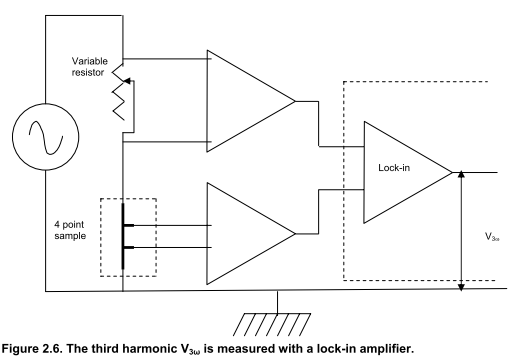
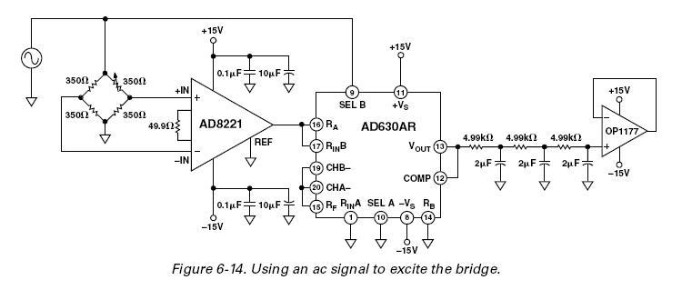
I'm implementing the so-called "3 omega technique", where a thin metal line is excited with a sine current. The metal has a high TCR which causes a 3rd harmonic oscillation, and I need to measure the amplitude of this voltage using a lock-in amp. I use a Keithley 6221 current function generator, which has high harmonic noise above 5 kHz, which interferes with the measurement of the 3rd harmonic.
In the litterature, several people have used a circuit such as the one illustrated in fig 2.6, pg 47 of this document : http://repository.lib.ncsu.edu/ir/bitstream/1840.16/5418/1/etd.pdf
The metal line is placed in series with a variable resistor with a low TCR, which is adjusted to the same nominal resistance as the metal line. Therefore by subtracting the 2 voltages, this will remove the fundamental signal, and harmonics caused by noise from the function generator, and the only thing left should be the 3 omega oscillation from the metal line.
However, I haven't found any detailed description of the actual circuit, other than the basic diagram in the link above. The only extra detail given by the authors is that they use AD624 amps.
So my question is, how do I actually implement this circuit ?
The 3rd harmonic is measured versus excitation frequency, which can vary between 1 Hz and 30 kHz. However harmonic noise from the generator isn't a problem at low frequency. The resistance of the metal line is typically 50 - 100 Ohm.
Thanks !
EDIT : my reputation is now high enough to post the diagram here directly 

