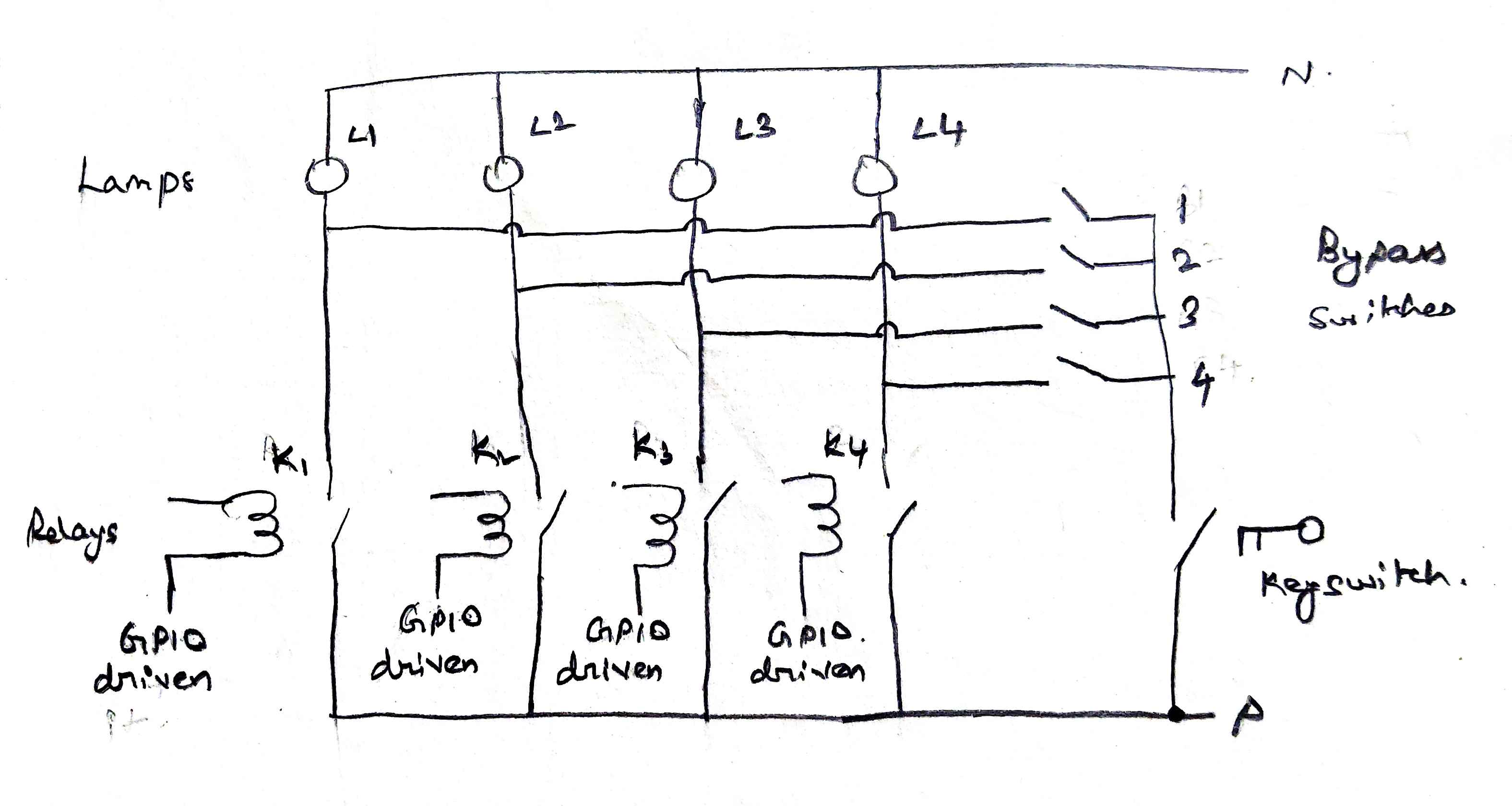
The lamps are normally operated by relays. When the relay or relay driving circuit fails totally, the bypass switches are to be used as fail-safe to operate the lamps. The key operated switch which is normally open (NO) at all the times, to be used when there is a relay circuit failure. The problem here is when say, relay 4 is on, and by chance switch 4 is also on, now it becomes easy to operate the lamps 1,2,3,4 normally with the switches making relay operation useless. The key operated switch has no use as well. Please suggest an alternative wiring using switches only to operate the load in case of relay circuit failure.
-
\$\begingroup\$ how do you intend to detect that the relay has failed? \$\endgroup\$– HearthCommented Dec 21, 2023 at 6:30
-
\$\begingroup\$ Are you saying that you want to to disable the function of the relays when the Key Switch is closed? Or are you worried that with the Key switch in the off position one manual switch closure could affect other circuit lines? If you could create a sort of truth table of what you need maybe the requirement will be clearer. \$\endgroup\$– NeddCommented Dec 21, 2023 at 6:30
-
\$\begingroup\$ Hi Nedd, Key switch and manual switches 1,2,3,4 are failsafe switches. Key switch will only be operated if one or more relay's fails. I am worried if any manual switches operation will affect my circuit lines. \$\endgroup\$– KumaranCommented Dec 21, 2023 at 7:01
-
1\$\begingroup\$ Of course the switches will affect your circuit lines! If they didn’t then the switches would be useless. Specifically, what are your concerns? \$\endgroup\$– KartmanCommented Dec 21, 2023 at 7:05
-
2\$\begingroup\$ I don't understand the intention here - aren't those the relay coils? Wouldn't you rather be looking at bypassing the relay contacts in case of failure? Note that a relay contact can get stuck in both open and closed positions, depending on the type of error (oxidation, welding, mechanical wear etc). \$\endgroup\$– LundinCommented Dec 21, 2023 at 9:00
1 Answer
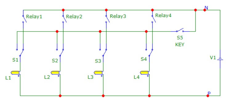
In your original circuit if two or more by-pass switches were left in the enable position (with the key switch off), there is the possibility that a working relay on one of those lines could inadvertently turn on two or more lamps.
If you were to change the arrangement a bit and also use SPDT by-pass switches the relays can be completely isolated and above unintentional operation could be avoided.
In the circuit below each SPDT by-pass switch (S1,S2,S3,S4), will select either the NO pin of a relay or the key switch line.
If the key switch is enabled (closed) each by-pass switch can manually light a single lamp circuit.
If the key switch is disabled (open) any combination of by-pass switch positions will not cause an extra lamp to light up even if a relay were to switch.
The only potential issue is that if a by-pass switch is left in the by-pass position and the key switch is disabled the lamp in that line will always be disabled even if the corresponding relay were to operate.
If you had to have absolute full manual control for each lamp (for example to over ride a relay stuck in the on state or off state), you could go a step further and select SP3T by-pass switches. That would allow you to have three operating modes: A manual on mode, a relay control mode, and a manual off mode.
.
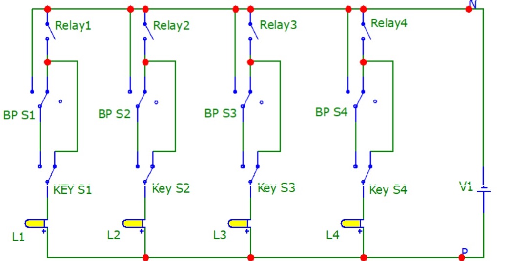
If you ultimately need to have full control in addition to preventing any issues with unintentional positioning of the by-pass switches then you should also use four separate key switches. If you don't use 4 separate key switches there is the chance that a working system relay could be inadvertently by-passed. The key switches (shown as "KEY Sn") would need to be SPDT types.
In the second circuit below when the corresponding key switch is disabled (set to the right) the main relay controls that line and any unintended positioning of the by-pass switch will have absolutely no effect on that line or the other lines.
When an only when the corresponding key switch is enabled (set to the left) will the single by-pass switch gain full control of the lamp (load) in that line.
As shown with SP3T by-pass switches (shown as "BP Sn") the by-pass options would include On-Relay-Off. The by-pass Relay position could be useful when someone gets around to changing a defective relay and would like to test it prior to a supervisor resetting the key switch. If one of these options is not needed you could use a SPDT type switch here.
.
-
\$\begingroup\$ Thanks for your suggestion. Like you already mentioned as potential issue, inadvertently flipping the manual switch will render the relay unusable... If we use SP3T switch too, unintentional operation of switch will lead to relay unusable. Awaiting alternate idea. 💡 \$\endgroup\$– KumaranCommented Dec 21, 2023 at 13:06
-
\$\begingroup\$ Primary operation is through relay only, if by chance relay or relay driving circuit fails, only then manual switches will be used for operating the load… source supplied through key switch. \$\endgroup\$– KumaranCommented Dec 22, 2023 at 0:58
-
\$\begingroup\$ @Kumaran - I've added a second circuit that will allow full control and prevent any unintentional by-pass switch problems. If there is still an open issue please create a simple truth table of your full requirements and include it with your original question. \$\endgroup\$– NeddCommented Dec 23, 2023 at 10:32
-
\$\begingroup\$ Hi Nedd, This helps, or I can simply use 4 key switches in parallel to relay contacts. My struggle here is not having enough room to mount them. I have decided to modify bypass switches to be operated parallel with relay contacts then mechanically lock the switches in open position. If bypass operation is needed then, mechanical interlock need to be removed. \$\endgroup\$– KumaranCommented Dec 24, 2023 at 1:55


