2
\$\begingroup\$

I have built a motor controller for my sewing machine that controls the motor speed rather than just controlling the power - in use, it is like the difference between using a soldering iron with temperature control instead using a soldering iron with a simple power control. Typical sewing machine foot pedals control only the power - mine controls the speed using a tachometer.

I used the controller for several hours over several days. It did what it was intended to do, namely make it much easier to sew leather and nylon webbing.

While I was doing some experiments to see if I needed to do anything to reduce RF interference (listening to an AM radio while running the machine under various loads,) the 16 ampere circuit breaker in the house tripped and the 2 ampere fuse in the controller exploded - literally. The fuse blew with such violence that there was nothing left of it but the metal end caps and some glass splinters.

Parts D1, D2, and Q1 all failed. D2 was shorted. Q1 had a short from drain to source. D1 had a short from the AC input to the "+" terminal.

I found that I had used a bridge rectifier (D1) rated for 400V instead of the intended 600V, so I replaced all the dead (shorted) parts (and replaced the rectifier with one rated for 800V) and tried again. It ran for a few minutes, then blew again - the fuse exploded and the breaker tripped this time as well.

I originally had a UF4007 for D2, so I rebuilt everything and upgraded to a 1N5408 under the assumption that there was too much current for the UF4007. Again, the fuse exploded after just a few seconds and tripped the breaker.

I put an NTC in series with the fuse, and replaced all the blown parts (D1, D2, Q1) and tried one last time. This time, the fuse blew but didn't explode. The circuit breaker tripped as well.

At this point, I am out of ideas.

Things I've considered:

  1. Capacitor C4 (400VDC, 47µF) is damaged. If it were damaged, it should show some sign - bulged, burned, melted plastic sleeve, etc. It shows no obvious damage, and it seems to do its job. I made one try without C4. The motor couldn't maintain its speed. With C4, it maintains its speed, but then the fuse blows. I only ran it for a couple of minutes without C4, so maybe I just didn't run it long enough for it to "go off."
  2. Motor is damaged. The motor turns and runs, so it can't be shorted. If it had to do with the brushes or the commutator, I'd expect to see sparking when the fuse blows - but there is nothing.
  3. U3 (ADuM4120) is damaged. If the PWM signal were distorted, then Q1 (NTPF190N65S3H MOSFET) would turn on slowly and overheat, causing it to fail. Q1 fails shorted every time the fuse blows. If Q1 died first, then the motor would speed up. I know that Q1 can stand running the motor at full speed because I specifically tried that out while building the circuit - I made the motor run full speed by setting the PWM duty cycle to 100 percent to see that it would be OK.
  4. A short to protective earth somewhere in the motor or the controller housing. This is unlikely since it is always the 16 ampere circuit breaker for the outlet circuit that trips, not the household GFCI.

Datasheets:

  1. Q1, NTPF190N65S3H MOSFET
  2. D1, KBP308 bridge rectifier
  3. D2, 1N5408
  4. D2 alternative, UF4007
  5. I don't have a datasheet for the motor. It is a common 100 watt sewing machine universal motor made for 230VAC.

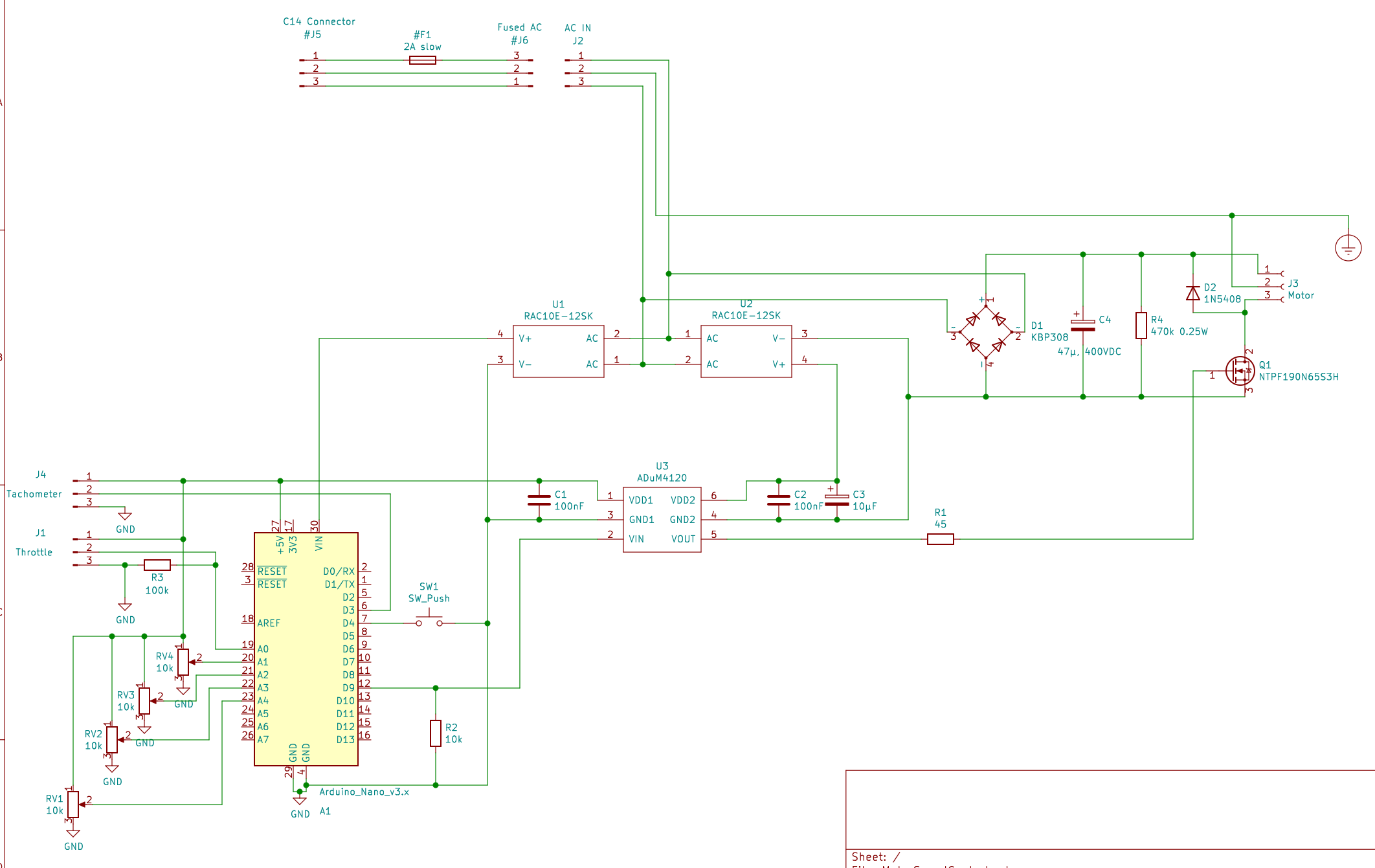
Circuit diagram:

enter image description here

The circuit diagram doesn't include the NTC resistor - I've only added it to the PCB as a tacked on experiment.

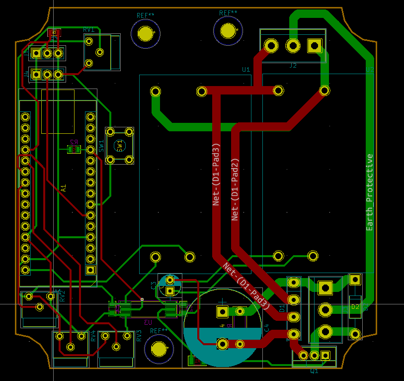
Layout:

enter image description here

Q1 is bolted to the aluminum box with a mica isolator between Q1 and the bare aluminum. I am honestly not sure how much good it does since the tab of Q1 is plastic.

The Arduino Nano is programmed as a PID controller. There's a foot pedal with a Hall effect sensor to provide the set point and an infrared photo-interrupter with a slotted disc to detect the rotation speed. Both are purchased modules that connect to the indicated headers on the PCB.

The PWM signal runs at 20kHz so I don't hear a squeal from the motor.

The circuit itself is on a PCB in a grounded aluminum box. I've also added a ground wire to the motor since the cheap things aren't grounded.


Edit: 2023.01.02

I've accepted Dave Tweed's answer. It gives some suggestions that I can follow up on to eliminate some possible sources of problems.

Spehro Pefhany's answer suggests a short through the coils caused by the insulation in the motor windings not being up to the high voltage pulses. I have no way to check that, except for correcting the things that Dave Tweed suggested then seeing if the fuse still goes bang.

Planned changes:

  1. RC snubber across the motor connections on the controller board.
  2. Replace D2 with a UF5408. I originally had a UF4007 there, then replaced it with the 1N5408 because of the higher current capability.
  3. Lower the PWM frequency to 5kHz.
  4. Limit the PWM duty cycle to 70 percent since the DC voltage is higher than the AC RMS voltage (suggested by Transistor in the chat.)
  5. Lower the gate resistor to 20 ohms.
  6. New PCB layout to address the creepage distance issues.

If none of that helps, then the problem may be with the motor. That would mean I have to scrap the project since the point of it was to make a better controller for the typical motors used on vintage sewing machines.

\$\endgroup\$
1

3 Answers 3

2
\$\begingroup\$

OK, after a long discussion in the chat, I'll offer these suggestions as an answer:

First, I would start looking at voltage stress on Q1. Universal (i.e., brushed) motors are noisy. Have you tried putting an R-C snubber across the motor (in addition to D2)? (Perhaps the snubber would be better placed directly across Q1 — I'm not sure.)

Second, looking at your layout, the creepage distances between high voltage and low voltage traces don't look like anywhere near enough to my eye. Especially between the gate and drain of Q1, but other places as well. If the motor is generating some short but very high-voltage spikes, they could easily be jumping any of these gaps. And if you're still using the same PCB on which the original failure(s) occurred, the board itself may be damaged, with excessive leakage across those gaps, which is just as bad.

Note that the clearance on the PCB, between the pads, is much less than the clearance between the pins on the transistor case. You really should spread those pins and pads out. The high-voltage MOSFETs that I've used in the past come in much larger packages with wider pin spacing to begin with. Given that you have the transistor standing perpendicular to the board, the most direct solution would be to bend the drain pin "up" (in the current view) and away from the other two.

Third, and way down the list at this point, while Q1 has high voltage and current ratings, its power rating is just an absolute max of 32 W with an ideal heat sink, given its thermal resistance of 3.88 °C/W junction-to-case. But I made some rough calculations of I2R and switching losses, and came up with only 10 mW and 300 mW, respectively.

\$\endgroup\$
1
  • \$\begingroup\$ Thank you for the suggestions. I'll work my way through them and see if they fix the problems. \$\endgroup\$
    – JRE
    Commented Jan 2 at 9:06
3
\$\begingroup\$

About the only thing I can think of that would cause the symptoms described with the troubleshooting sequence and wiring exactly as shown would be the motor momentarily shorting at the commutator and we'd also have to presume that both disparate kinds of diodes would break down in reverse (or they would not fail). Seems unlikely.

A more likely cause by my estimation might be some kind of short to ground. You are stressing the motor insulation more than in the usual situation by feeding it sharp PWM pulses with some kind of wiring in between (that will have inductance) and you've added a ground wire (which you helpfully included in the description, a rarity in these troubleshooting situations!).

Industrial motors designed for PWM control have better insulation ("VFD rated") compared to those just intended to be connected across the mains. There's also possibly the lower right corner of the PCB vs. the aluminum box as a short possibility. The second kind of short is an easy fix and easy to diagnose. The former would probably require swapping the motor out.

\$\endgroup\$
2
  • \$\begingroup\$ I think I can eliminate a simple short through the box as the cause - the box is powder coated inside and out. Even if a short through the powder coat is possible, I'd see arcing and burning. An intermittent short through the motor windings because the insulation isn't up to handling the PWM is something I can't directly check. I'll work my way through the suggestions that Dave Tweed made. If the controller still goes bang, then that would point to the motor insulation as the cause. \$\endgroup\$
    – JRE
    Commented Jan 2 at 9:11
  • \$\begingroup\$ Putting one fuse in series with each of the motor leads might help in the diagnosis. \$\endgroup\$ Commented Jan 2 at 15:02
1
\$\begingroup\$

From a design review standpoint, I would offer these general observations:

  • No line filter
  • No ESD protection or RFI filtering on the MCU
  • Only one line fused; a second fuse could be added to help rule out ground faults (but shouldn't be necessary as such). (Does seem unlikely, given the full-house GFCI.)
  • Fuse is definitely underrated, if it's exploding! Use a type rated for available mains fault current (at least a couple kA, perhaps even 10kA+). A ceramic type may be needed, or a larger "midget" type.
  • Diode needs to be fast-recovery type; motor inductance will be high enough to run in CCM (continuous conduction mode) even at fairly low throttle (though, see below).
  • Gate resistor is way too small, given the low switching frequency and lack of filtering.
  • Fast switching may drive transient voltages through the motor and wiring. Roughly speaking, the motor will have some RLC equivalent circuit at edge-related frequencies (say 10-100 MHz), which acts as a series resonant circuit or transmission line stub, developing a peak up to double the applied voltage. (Whether this actually occurs to a significant degree, depends on the RLCs.)
  • Beware motors with internal filtering. As brushed type motors are very noisy, they may be equipped with noise filtering, internally or inline in equipment wiring. This was not mentioned, so it's worth noting the possibility at least.
  • The control cannot sense load current

Also just to lampshade the elephant(s) in the room -- I'm guessing the massive 10W power supplies were already on hand? So I'm not dinging that as a design issue per se. (After all, what's better than a 0$ BOM item?..)

EMC Points

Of course, these probably aren't related to the observed failure; they're added more for completeness. Given you've been testing with a radio, maybe it's fine anyway; do mind to check at multiple frequencies across the band, particularly several adjacent channels at a time, as 20kHz harmonics could skip every other channel and you might simply miss it. (You could also pull a sneaky and make it some oddball 18.573 or whatever kHz, so the harmonics will land well within a channel somewhere. Or, this doesn't matter if it's an "old fashioned" continuously-tuned radio.) Likewise, given observations, maybe the MCU filtering is more nice-to-have rather than necessary; severity depends on software as well i.e. digital filtering / debouncing as well, which is not documented here.

Gate Resistor

Superjunction MOSFETs really are different beasts from what conventional wisdom says about MOSFETs. First I'll discuss switching speed in the application, then discuss SJ FETs.

Faster switching gains you nothing here: suppose allowable dissipation is 1W (none or small heatsink), and load current is up to 1A (well over 100W at 320VDC supply!). A triangular commutation waveform has a dissipation of (total rising plus falling), $$ P = V I F_\text{sw} t $$ or a time up to 0.16µs is tolerable. With a small heatsink, and limited to lower currents, a sizable fraction of a µs will be tolerable, pushing the cutoff for harmonics below 10MHz.

Note that turn-on incurs additional losses \$P_\text{on} = \frac{1}{2} V I_{rr} F_\text{sw} t_{rr}\$, for whatever peak recovery current and recovery time the diode has under the conditions (\$I_F\$ and \$dI/dt\$ at FET turn-on). Hold onto this thought for later.

Superjunction: the thing is, the drain capacitances (D-G and D-S) behave unlike anything you will find in textbooks, application notes (except for the scant few documenting this) or older books (or newer ones for that matter, when the author(s) simply aren't aware). It well and truly switches between high and low capacitance regimes, at a ballpark 10-50V threshold.

Datasheets plot the transition region as a steep capacitance curve, but in fact it is a discontinuity where, during the transition, capacitance is not a meaningful description of the process (the incremental capacitance may explode towards infinity, go negative, back and forth..). The curves look smooth because of measurement method (the discontinuity is smooshed out, more or less).

For EMC purposes, the impact is that gate resistance predominantly controls the propagation delay moreso than the voltage rise/fall time, and it controls \$dI/dt\$ to the extent that this parameter is determined by Ciss and the transconductance curve (as opposed to source inductance, which degenerates the effect of gate resistance). This is easiest to see looking at Vds vs. Vgs: the bulk of the Miller plateau is at low voltages; the voltage swing is dictated more by load impedance (and what drain capacitance is left) than by gate current.

For point of reference, I have a design with 105mΩ transistors (same family, different part) driven with a 22Ω gate resistor. The Vds rise time is ~10ns, giving more-or-less minimal switching loss.

At least several hundred Ω gate resistance seems appropriate here, perhaps up to the low kΩ.

To control \$dV/dt\$, then, we can put back a controlled amount of CDG. An R+C is suggested, to dampen potential VHF oscillation. \$dI/dt\$ can be limited by adding source inductance (perhaps a ferrite bead or several?).

Example value would be, let's say... 300V swing, 100ns time, 100Ω gate resistor with 12V drive and 4V Miller plateau = 8V dropped across the resistor or 80mA, so 80mA * 100ns / 300V = 27pF. With a series resistor of 100-1k Ω, say.

Motor Paranoia / Filtering

This is kind of just, good reasons to filter the output in general, and as mentioned, harmonics or transients can drive peak voltages internal to the windings, or across brushes/commutator, etc.; or if filtering is already present, likely it's not of an impedance and topology friendly to the buck converter and results in large peak currents, excessive ringing, and probably poor PWM control too.

The existence of a motor EMI filter is easily verified by inspection, of course. Mind, it could be internal to the motor, which needs to be inspected as well. (Rare I would think? But possible.)

Now, output filtering doesn't need to be total; a small series L, then shunt R+C, could be used to chop off the highest harmonics, and give a controlled impedance that acts to terminate or dampen whatever reactances reside in the motor. Typical values might be 3.3µH, 330pF and 100Ω.

The downside of a partial (harmonic cut) filter is, its peak current is drawn through the switch every cycle, so still has some voltage overshoot, and the peak current draw increases losses (in addition to the charge in the capacitor, which is burnt in the resistor).

A full filter would be reasonable for a higher switching frequency (100kHz say); typical values might be 1.8mH + (33nF || (100nF + 220R)). Cutoff below Fsw avoids wasting harmonic currents, but, obviously, it's much bulkier too.

Current Mode Control

This is recommended for many reasons: torque control, splitting the output filter poles (when LC filtered; most often for PSUs), electronic protection and potential reduction of cascade failures, etc.

Granted, in a simple application like this, I probably wouldn't bother either. But I might consider some mitigation in lieu of it: using an overrated transistor (check!), adding series resistance (a nice big resistor and thermal cutout would probably do fine), even doing the whole damn thing linear isn't out of the question, assuming adequate heatsinking is available. (I have some power transistors on hand that can do this ably; that would look like: a regular phototransistor opto, from +V to G (and divider and G-S pull-down resistors, and zener clamp), for drive; generous source degeneration to set current range; and a PWMDAC and filter would furnish analog control from the MCU. The digital isolator/driver and 2nd power supply would be eliminated. The MCU too could be eliminated, if you're comfortable with analog PID controls and some logic as applicable, but doing it digitally is fine, too.)

Diode Recovery

This is not to be underestimated, especially for slow recovery types. For point of reference, even the SMPSs of the 70s, running hardly over 20kHz, used what fast rectifiers were available -- maybe 200-500ns in those days, but they were still better than the general-purpose types. As mentioned, the problem is significant: even if recovery current equals load current, if it lasts for a microsecond, that's a lot of power dissipation. Worse, it compounds: it has positive tempco. Even fast-recovery types can run away with modest heatsinking; worst-case heating must be accounted for.

The long time constant before failure further supports a thermal mechanism. Particularly at medium duty cycles where average diode current is maximum. Were hot components noted? (Was it just buttoned up and expected to work? Maybe there was no chance to check...)

tl;dr

A fast recovery rectifier should do the trick. A schottky (SiC) could even be used, rather overkill, but they are nice.

Check component temperatures, and add heatsinking as needed.

Increase gate drive resistance, and add snubbing elements as needed.

Check waveforms to make sure nothing squirrely is happening, the edge rates are as intended, and the motor isn't getting bounced around.

A current sensor might be helpful to prove motor current and verify it's not doing anything you would miss with voltage probing alone. A simple way to construct a clip-on current transformer is to use a large enough split-core ferrite bead with ten or so turns of fine wire, terminated into 50 ohms. The frequency response won't be anything impressive, but it'll pick up the high-frequency blips and pings we're looking for here.

\$\endgroup\$

Your Answer

By clicking “Post Your Answer”, you agree to our terms of service and acknowledge you have read our privacy policy.

Not the answer you're looking for? Browse other questions tagged or ask your own question.