0
\$\begingroup\$

I am currently working on diagnosing the functionality of a thermocouple from a vintage gas stove, whose safety valve does not stay open with the pilot light heating the hot end of the thermocouple.

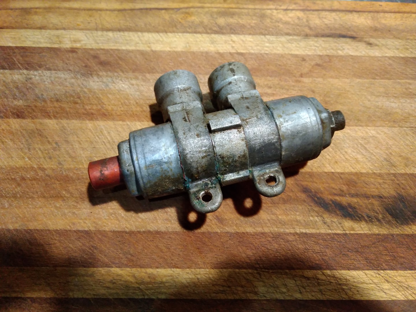
The valve is fairly encrusted with grease, yet this resistance would seem to assist the thermocouple after opening the valve manually. The goal at the moment is assessing whether the thermocouple is functioning electrically to determine whether this component needs replacement or repair.

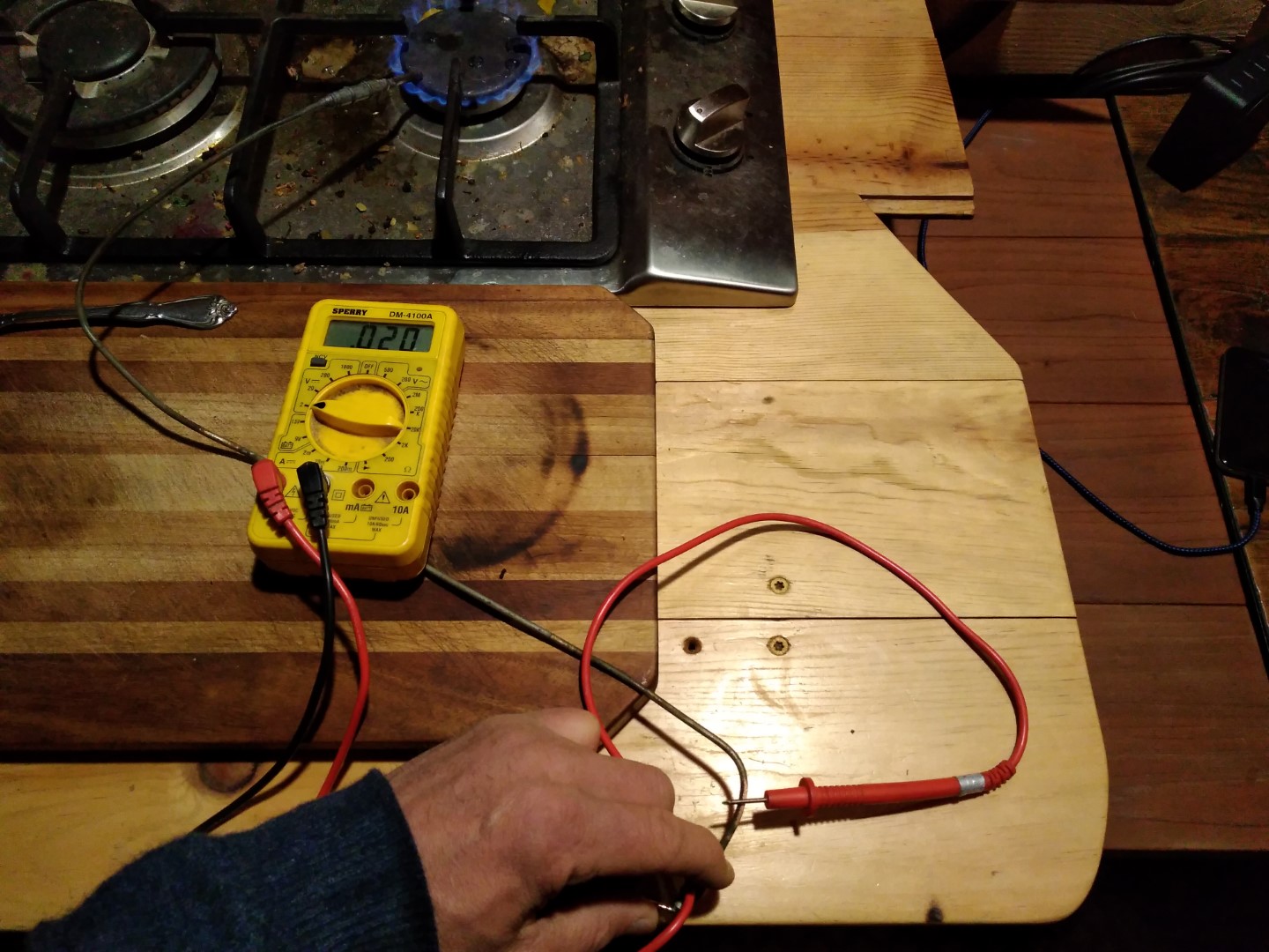
This is also a question of reading incongruous values when measuring milliamps. As for voltage, when exposing the hot end to flame with the probes connected to the copper sheath and cold end, the device produces a maximum of roughly 15 - 20 mV.

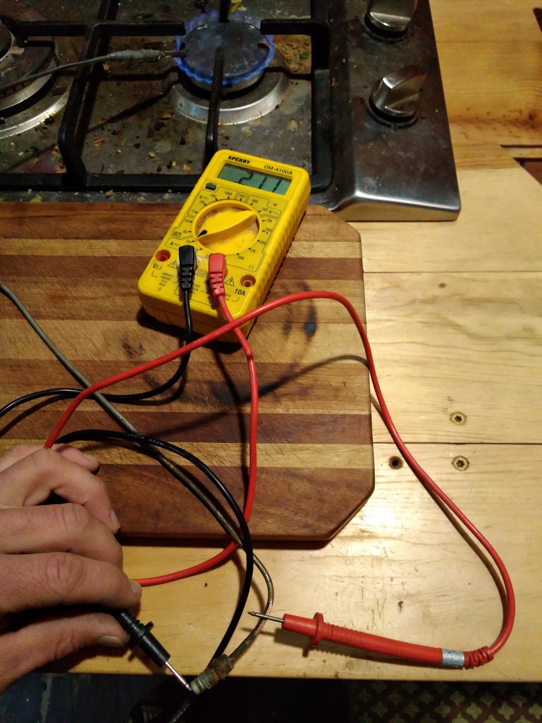
20 mA voltage reading

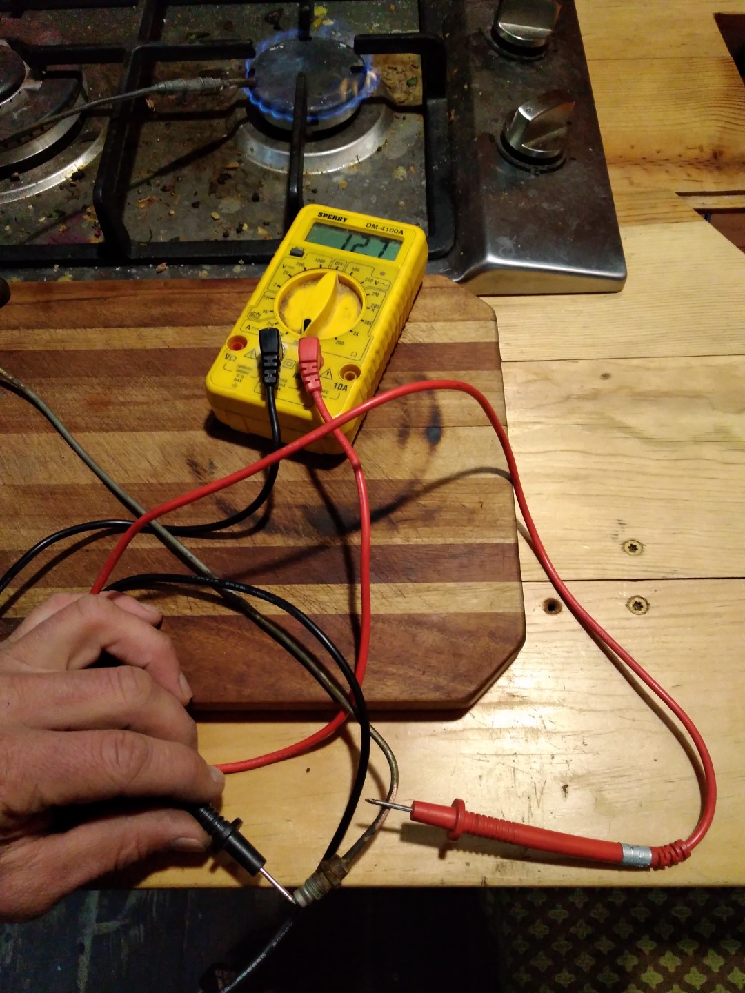
With the meter configured for mA values, the readout is 0.211 in the '2m' position and 12.7 in the 200m position. I want to say the thermocouple is producing 211 mA but I would think the '200a' setting would increase the value by two orders of magnitude but it also cuts the value down 60%. I would like to know the precise current here and do not know to rectify these two numbers.

2m position

200m position

Essentially I am trying to discern if these values are typical while suspecting the valve or if they are low and indicate a failed thermocouple. I think a sticky valve would assist a thermocouple in keeping the valve open after manual engagement.

safety valve

\$\endgroup\$
2
  • 1
    \$\begingroup\$ The thermocouple is essentially a voltage source (with the 15-20 mV Seebeck voltage you've measured) in series with a tiny resistance (which might be completely insignificant for your application). When you try to measure its current, it depends on the multimeter internal resistance, which is not negligible compared to the thermocouple resistance and depends on the current range you choose. Is there a reason you are trying to measure the current? \$\endgroup\$
    – Puk
    Commented Jan 14 at 4:59
  • \$\begingroup\$ @Puk This appears to be a directly operated gas valve, so the resistance is important. \$\endgroup\$ Commented Jan 14 at 6:16

1 Answer 1

1
\$\begingroup\$

You will never get a good current reading (a reading indicative of the short-circuit current) with a regular multimeter when the open-circuit voltage is so low. The multimeter on a DC current range has to drop a lot of voltage compared to a thermocouple output. The meter will read the current through it, but that current will be less (perhaps much less) than the short-circuit current, or likely the current through the gas valve coil.

Your meter has a full scale burden on the 200mA range of 350mV. So it appears as a 1.75Ω resistor. It's possible to estimate the thermocouple resistance from the open-circuit voltage and the current reading on that range, but the readings would have to be taken under the same conditions (stable temperature) or the results would be garbage.

Your open circuit voltage is in the generally normal 15-35mV range from what I know, and the fact it passes more than 10mA indicates it isn't quite hanging by a thread, but there may be nuances with your specific equipment.

I think this question should be migrated to the DIY SE if you need further clarification or for additional questions that may arise.

\$\endgroup\$

Your Answer

By clicking “Post Your Answer”, you agree to our terms of service and acknowledge you have read our privacy policy.

Not the answer you're looking for? Browse other questions tagged or ask your own question.