The NPN bipolar junction transistor (BJT) has a base which can never be more than about 0.7V above its emitter in potential. Algebraically that is:
$$ V_B - V_E < 0.7V $$
The difference \$V_B - V_E\$ if most commonly written \$V_{BE}\$ , so another way of saying the exact same thing is that the base-emitter junction (which behaves just like a regular silicon diode) inside the BJT can never have a voltage \$V_{BE}\$ across it that exceeds 0.7V:
$$ V_{BE} < 0.7V $$
Think of that B-E junction (or a diode) as a piece of string with length 0.7m. You can freely separate the two ends by any amount, but when the separation is 0.7m, the string becomes taught and prevents you increasing the separation any further.
A light-emitting diode, LED, has similar behaviour, but the maximum voltage across it (called the "forward voltage" or \$V_F\$) is somewhat higher, and depends on the LED. When somebody says \$V_F=1.7V\$, what they mean is that this is the maximum potential difference across the LED, when it's fully lit, because the LED itself will oppose an increase beyond that. It's like a string with length 1.7m.
In the string analogy, this behaviour occurs because the string suddenly becomes very stiff and taught. In electronics the same thing happens because the device suddenly becomes extremely conductive. Here you have two strings of length 0.7m and 1.7m joined end to end. The largest distance you can separate the two free ends is \$0.7m + 1.7m = 2.4m\$
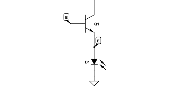
In the circuit you have shown us, you have a base-emitter junction in series with an LED, like this:

simulate this circuit – Schematic created using CircuitLab
I'll assume the LED has \$V_F=1.7V\$
What this tells me is that the potential at the bottom of LED D1 is held at 0V (that's what the ground symbol means). The potential \$V_E\$ of node E, at the top of D1, cannot exceed \$0V + V_F = 1.7V\$. The potential \$V_B\$ at B cannot ever rise above \$V_E + V_{BE} = V_E + 0.7V = 0V + 1.7V + 0.7V\$. In other words:
$$ V_B < 2.4V $$
If you try to raise \$V_B\$ above that, both base-emitter junction and LED will become very, very conductive, passing whatever current they need to prevent their \$V_{BE}\$ and \$V_F\$ from increasing further.
The behaviour of a resistor is not like a string, it's more elastic. You can separate the ends of the elastic to any distance you like. It opposes more and more the harder you pull the ends apart, but there's no limit. Electrically this means that the resistor simply passes more current, the greater the potential difference you try to impose across it. In fact current \$I\$ through a resistor is always proportional to voltage \$V\$ across it, and the constant of proportionality is its resistance \$R\$, giving rise to Ohm's law:
$$ V = I \times R $$
It won't suddenly become more conductive (or less conductive) when the voltage across it reaches some threshold, like a diode or base-emitter junction would. It retains the same electrical resistance always.
Let's put a resistor in the chain:

simulate this circuit
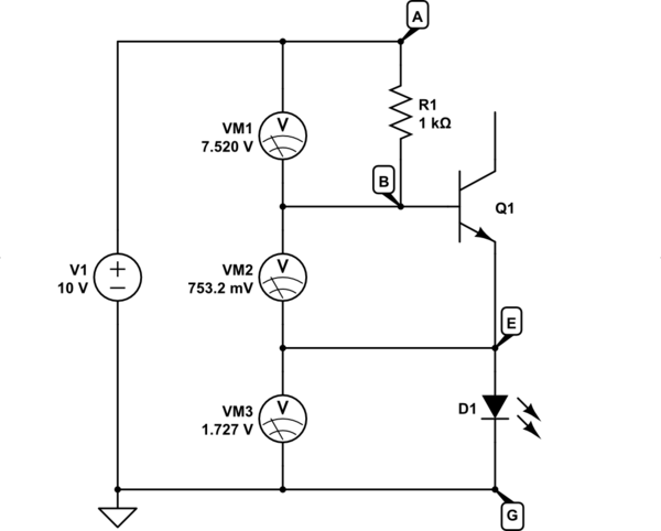
I've also added a few voltmeters to see how far we've "stretched" the three elements. I've placed 10V across the chain. In my analogy this would mean that I've tried to stretch ends A and G 10m apart. In your mind I'm sure you see that the two pieces of string \$V_{BE}\$ and \$V_F\$ are taught and rigid now, and can't get any longer, so the resistor must have stretched to cover the remaining distance.
That's what you see on the voltmeters. VM3 shows you the potential difference across the LED, which has been capped at 1.7V. The base-emitter junction is unable to have more than 0.7V across it, as shown on VM2. The remainder must be across resistor R1, shown on VM1.
If you didn't have R1 in place, and V1 was tied directly to B, you can imagine what would happen. You'd be stretching the two strings beyond their breaking point, and one or the other (or perhaps both) will snap.
Sticking with the analogy, if \$V_1 < 2.4V\$, that means the two strings are not extended to their maximum lengths. There's no tension in the system, and R1 would not be stretched at all. In electrical terms this corresponds to zero volts across the resistor. The entirety of V1 must be shared between D1 and Q1. It's only when the strings become taught that R1 begins to "stretch", the voltage across it beginning to rise.
Analogy over. From now on I refer to potentials and potential differences only. I will use the convention that \$V_{XY} = V_X - V_Y\$. That is, in the circuit above:
- The potential difference (voltage) across R1 is: $$ V_{AB} = V_A - V_B $$
- The potential difference across Q1's base-emitter junction is $$ V_{BE} = V_B - V_E $$
- the potential difference across D1 is $$ V_{EG} = V_E - V_G = V_E - 0V = V_E $$
- The potential difference across source V1 is $$ V_{AG} = V_A - V_G = V_1 $$
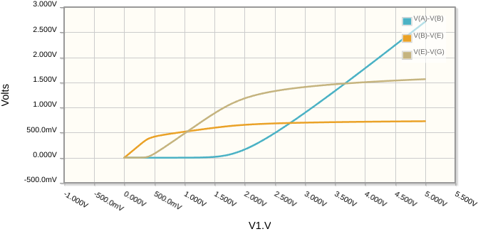
In the following graph I sweep \$V_1\$ from 0V to 5V, and you can see how the voltages \$V_{AB}\$ (across R1, blue), \$V_{BE}\$ (across Q1, orange) and \$V_{EG}\$ (across D1, tan) respond:

As expected, \$V_{BE}\$ and \$V_{EG}\$ begin to rise as soon as \$V_1\$ starts increasing from 0V, and each continues to rise until it "meets" its maximum, 1.7V and 0.7V respectively. R1's voltage \$V_{AB}\$ doesn't begin rise until Q1 and D1 have reached their caps.
These curves don't have sharp corners. All the descriptions I made above are somewhat approximate. The diode doesn't suddenly become more conductive at \$V_F=1.7V\$, and the transistor doesn't suddenly become more conductive at \$V_{BE}=0.7V\$. These transitions between states are much more gentle and smooth in reality.
For all values of \$V_1\$, this condition is obeyed:
$$ V_{AB} + V_{BE} + V_{EG} = V_1 $$
Stated in words, that says that the sum of the voltages across each element must equal the total voltage applied across them. This is Kirchhoff's Voltage Law (KVL).
The main takeaway here is that while you've been told that the base voltage can't be greater than 0.7V, that's not true. It's the difference between base and emitter potentials that cannot exceed 0.7V. If the emitter is permitted to rise in potential, as D1 permits here, then of course the base can rise with it, well beyond any "absolute" limit of +0.7V.
Therefore, in your circuit, the maximum base potential permitted is +2.4V, not the 0.7V you assumed.
Also, you mentioned a "boolean" response. That's not possible here for two reasons:
the voltage across the LED will rise almost linearly with base potential, as shown in the graph. This is very far from the "on/off" behaviour you desire.
the system doesn't have any sharp changes in behaviour, also shown in the graph. Everything is smooth. There are ways to produce sharper responses, but this circuit won't have that.
I won't address further workings/failings of your original circuit beyond that, because it's pointless until you've properly grokked everything I wrote here.


