0
\$\begingroup\$

I'm working on a small project, where I read up-to 12 brightness values from light dependent resistors (my schematic below only shows three). The basic layout is a voltage divider per sensor, which is feed into one of the ADC channels of a teensy microcontroller.
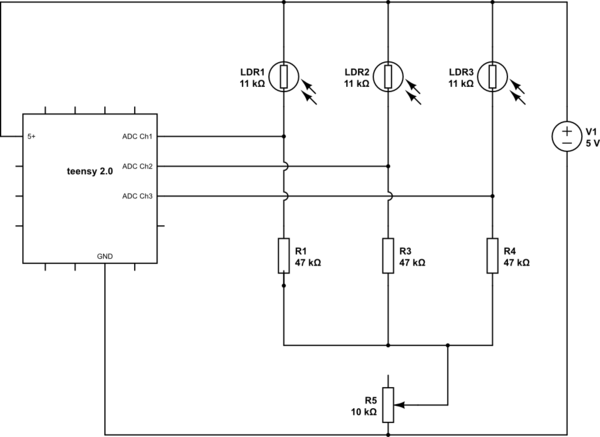
schematic

simulate this circuit – Schematic created using CircuitLab

From the ADC I get a pretty good reading from 20-1000. I actually tried different resistor values for the voltage divider (R5) and I ended up with 47kOhms.

In some environments, I have lower light and I would like to make the voltage divider adjustable. With low light, my readings only go to 200-300.

I've tried to add a potentiometer, but this does not work. I'm not 100% sure why to be honest. Is there another way to do this? I want to have ONE adjustable potentiometer to change the voltage dividers on all channels.

\$\endgroup\$
2
  • \$\begingroup\$ A potentiometer has three connections. The resistance between two of them is fixed. The third terminal has a variable resistance to the other terminals that changes as you turn the knob. Your diagram shows the two ends (fixed resistance) connected, and the third (variable) is not connected. So, no surprise that you can't use it to change the sensitivity. \$\endgroup\$
    – JRE
    Commented Feb 25, 2017 at 12:47
  • \$\begingroup\$ sorry, that was a mistake, I've edited the schematic \$\endgroup\$
    – Chris
    Commented Feb 25, 2017 at 12:52

3 Answers 3

1
\$\begingroup\$

You want high dynamic range... but you don't have enough bits. Here is a hack.

Let's suppose you want to measure your LDR's resistance from 100 ohms to 1 MOhms with decent precision...

Remove the resistors, and replace them with 10nF C0G or film caps. Now...

  • Set ADC pin to digital output, and output 0V.
  • Wait 100µs
  • Set ADC pin to high-Z analog input
  • Wait for a time delay T
  • Acquire analog value

Now, depending on time delay T, the capacitor will have more or less time to charge through the LDR. In order to measure a much higher LDR value, simply wait longer for it to charge! This gives you easy range switching without any extra parts or pins.

Other solutions include :

  • ADCs with more bits
  • Analog MUX followed by variable gain amplifier
  • dannyf's proposal above
\$\endgroup\$
0
0
\$\begingroup\$

Use GPIO pins to short the dividers through different resistors to obtain different "sensitivity".

\$\endgroup\$
-1
\$\begingroup\$

If you are not careful you will end up with a LOT of I/O lines. What I would do is to use a 16-channel analog multiplexer to switch all the LDRs to a common digitally-controlled pot, and read the voltage from that. This way you need only 7 lines - 4 for the 16-way address, 2 for the SPI lines to the pot, and the ADC input.

OK it takes more ICs, but you lose 12 resistors and 5 I/O lines.

\$\endgroup\$
1
  • \$\begingroup\$ This idea is not helpful for the OP. The question was not about saving analogue I/O pins on the microcontroller. In fact there are many small devices that have built in analogue multiplexers as part of their A/D converter and it appears that the OP wants to leverage that to his advantage. \$\endgroup\$ Commented Feb 25, 2017 at 12:53

Your Answer

By clicking “Post Your Answer”, you agree to our terms of service and acknowledge you have read our privacy policy.

Not the answer you're looking for? Browse other questions tagged or ask your own question.