I'm trying to figure out how to set R1 + R2 on the LM431 shunt regulator. I have input V+ that I can't change at 9 V and I want Vout at 5 V. What value of resistors should I use for that? How does the Vref value change?
2 Answers
\$\begingroup\$
\$\endgroup\$
2
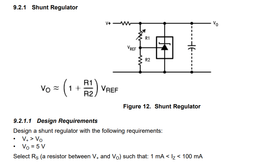
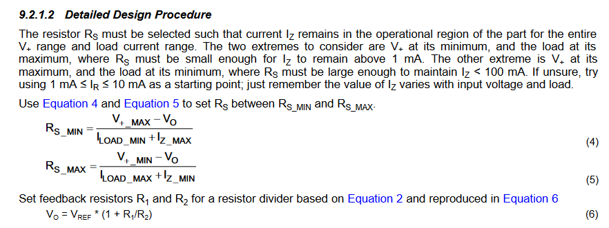
That drawing is from the LM431 datasheet. All you need to do is to follow the detailed design procedure given immediately after the drawing.
Hints:
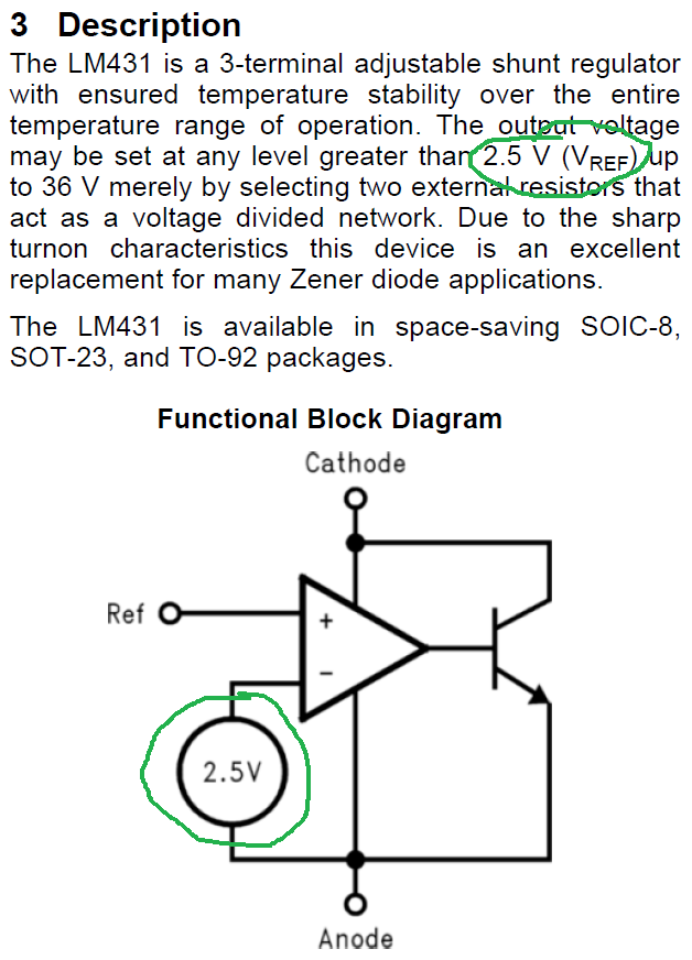
- \$V_{REF}\$ is a fixed value given several times in the datasheet.
- There's a completed example in the design procedure that matches your task.
-
\$\begingroup\$ Oh, I didn't notice that Vref is a fixed value... Then it makes sense that when R1=R2 the output voltage will be 5 V. Thank you very much \$\endgroup\$ Commented Feb 27 at 15:56
-
\$\begingroup\$ @Simplifier That's correct. On Section 6.5, it gives you a table of this. When you design your solution, you have to consider the behavior of the entire inside circuitry of the device described in that table (and there's another table that says something like "Absolute Maximum Ratings" as your boundaries of limitations). But congratulations! You designed your first part :) \$\endgroup\$– ColinCommented Feb 27 at 16:01
\$\begingroup\$
\$\endgroup\$
From the 1st page of the datasheet:
And no worries - there have been plenty of times I've looked everywhere but the 1st paragraph on the first page of a datasheet, technical standard, etc. I can only sympathize.


