2
\$\begingroup\$

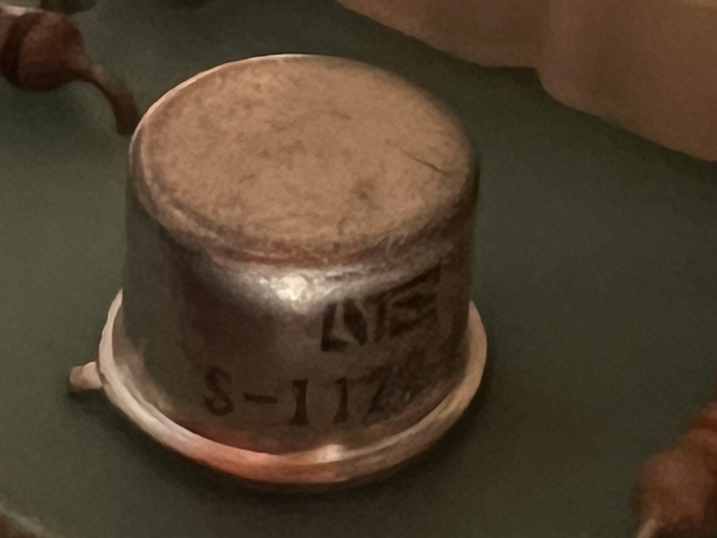
I am debugging a mid-1970s piece of printer equipment and have traced a failure to what looks like a bad transistor. But I can't find a data sheet for it (or a useful substitution). It's a metal can labeled S-1122 (with the old National Semiconductor logo on it). In the documentation for the printer device it's called an "SS1122 PNP transistor". This part seems to have been used in multiple Southwest Technical Products kit devices of the era, but I cannot find it in any of the National databooks I can locate online and googling around doesn't turn up much else of that vintage.

enter image description here

This old thread on DIYAudio talks briefly about it and suggests a substitution ("2n5415, 2n5416") but I'm not sure on what basis.

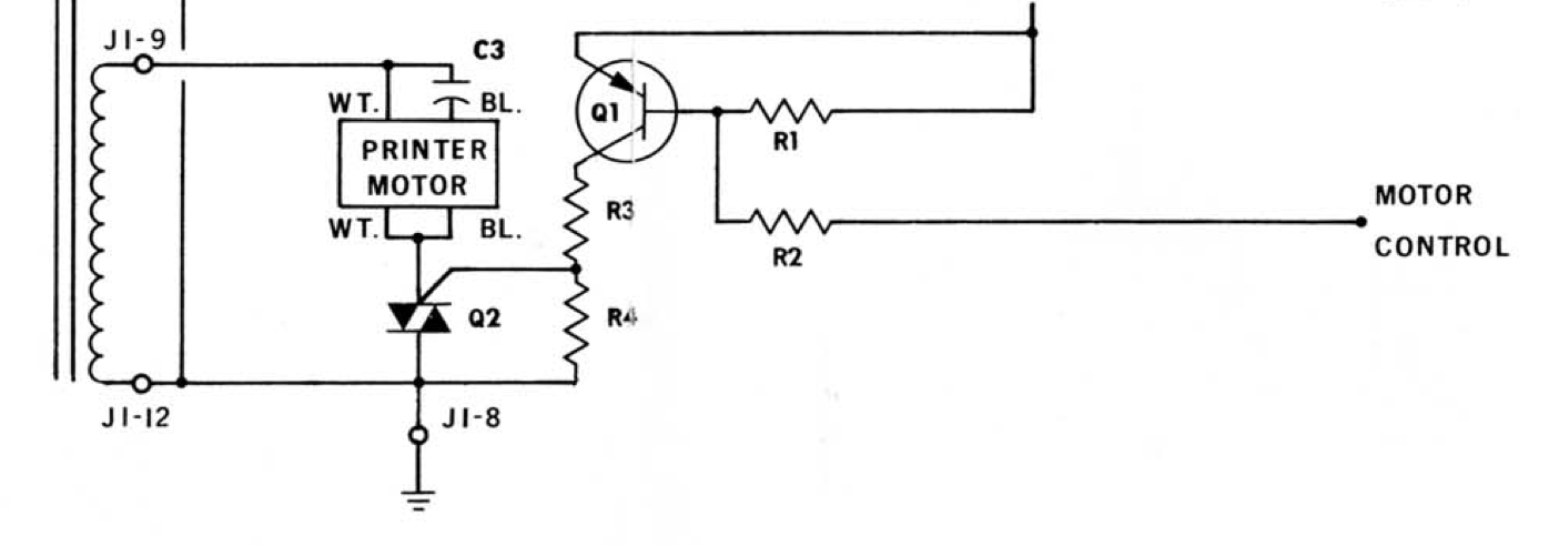
The 1122 part is being used in this circuit (excerpt, click for full schematic) labeled Q1:

enter image description here

The "motor control" line is a TTL signal that goes low to turn on the AC motor via Q1 and the triac. (The voltage divider at the base of Q1 turns a "low" TTL signal into about 2V where there is 8V at the emitter.)

Can anyone help me find a data sheet for this part, or I suppose failing that, help me identify a useful substitution for this application? Thanks!

\$\endgroup\$

1 Answer 1

4
\$\begingroup\$

This is a low-load application, only used to turn on the gate of a triac. The exact specs of the transistor largely don't matter other than the voltage rating.

Only about 20-30mA flows through the transistor when it's on. The motor looks like it may run on 50-100V, so it'd be best to use a transistor rated for 200Vceo at least.

The jellybean go-to choice for that would be MPSA92.

This old thread on DIYAudio [...] suggests a substitution ("2n5415, 2n5416") but I'm not sure on what basis.

The substitution is based on the identical case and suitable Vceo (250-350V for 2N5415/5416 respectively).

If you're going for authentic look/restoration, 2N5415/6 are good substitutions since they should be direct fit. If I was repairing the printer for my own amusement only, I'd just stick an MPSA92 there since I got a bunch of them already.

One suggestion though: do not solder the replacement transistor so close to the PCB. It puts quite a bit of stress on the pins and the hermetic seal around them as the temperatures change. There should be at least 5mm of lead between the component side of the PCB and the transistor.

\$\endgroup\$
2
  • \$\begingroup\$ Thank you for this. I follow most of your explanation but I am a bit confused about the transistor needing to support high voltage— the triac plainly sees the higher ac voltage, but I don’t follow why the transistor in question would. My understanding is that the gate of the triac doesn’t need more than a volt or two to switch on, and Q1’s emitter sits at 8V max. What am I misunderstanding? Thanks \$\endgroup\$
    – BZo
    Commented Mar 17 at 21:40
  • 1
    \$\begingroup\$ Transients and good engineering practice of being conservative when connecting to circuits that are galvanically attached to mains. \$\endgroup\$ Commented Mar 18 at 14:02

Your Answer

By clicking “Post Your Answer”, you agree to our terms of service and acknowledge you have read our privacy policy.

Not the answer you're looking for? Browse other questions tagged or ask your own question.