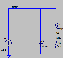
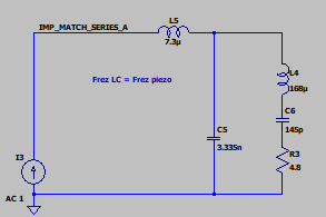
I am at the stage of designing a system that match impedance of the power output (half-bridge) to a piezo transducer operating at 1MHz (Max 60W of power). I calculated the piezo parameters from the impedance measurements and compared the model impedance graph with the measured impedance graph (the graphs are similar).
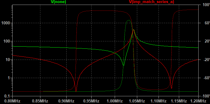
Most scientific sources propose a matching system made in such a way that it consists of a series inductor and a capacitance parallel to the piezo. Since the piezo already has such a capacity (C1 in my diagram), the coil itself is enough. The authors propose to select the coil so that the resonant frequency of the coil from the matching system and C1 is the same as the piezo mechanical frequency represented by the L1, C2 and R1 branches (In the work A High-Tolerance Matching Method against Load Fluctuation for Ultrasonic Transducers, the authors propose that the resonance of coil with the piezo capacitance should be the square root of the 2 of piezo resonance frequency). However, after selecting such a coil, the resonant frequency of the system changes for some unknown reason.
The questions I can't find answers to are:
- Is tracking this new frequency (in the case below 919kHz instead of 1.020MHz) the optimal strategy for delivering maximum power to the piezo?
- Isn't providing a signal at a new frequency bad because it is not the mechanical frequency of the system?
- If so, why is this method so popular? Are there better methods?
Simulations:
Scientific articles:
- A high-tolerance matching method against load fluctuation for ultrasonic transducers
- Review of the design of power ultrasonic generator for piezoelectric transducer
- Design and construction of a prototype of an ultrasonic applicator for ultrasonic soldering, cutting and drilling
- Effect of the Matching Circuit on the Electromechanical Characteristics of Sandwiched Piezoelectric Transducers


