1
\$\begingroup\$

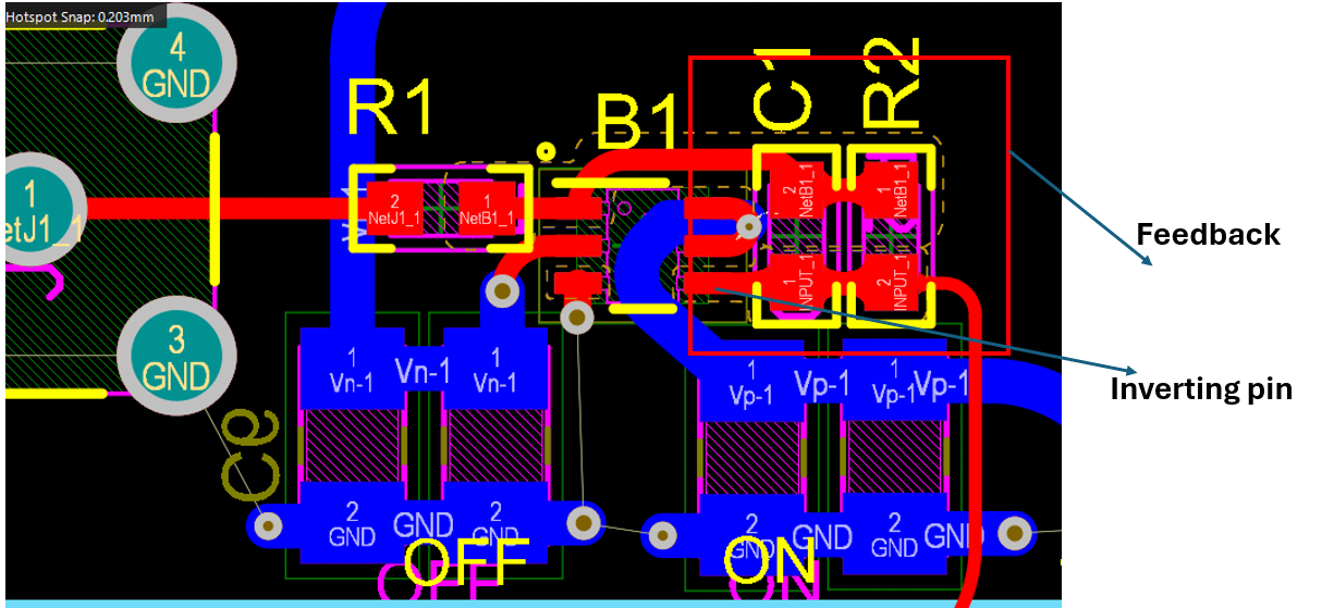
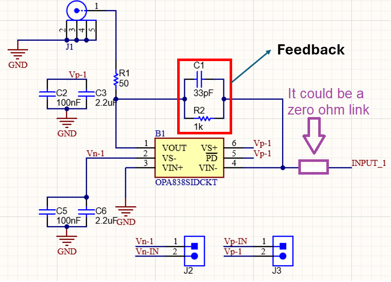
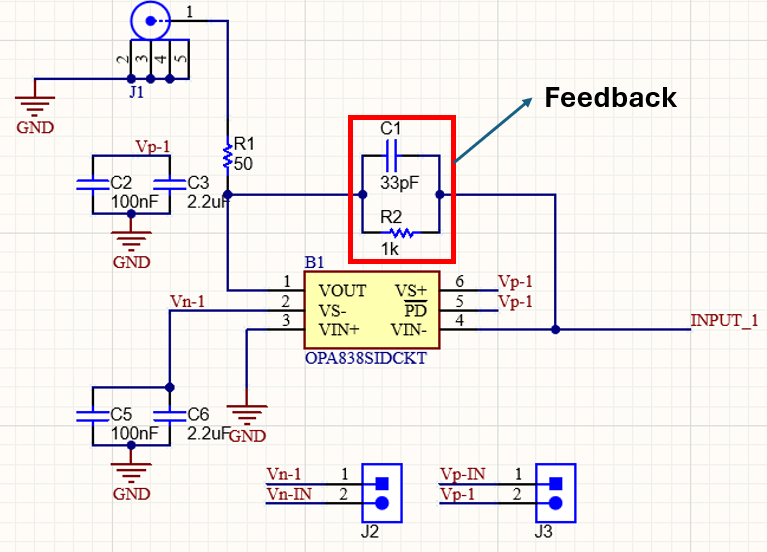
In closed-loop operation amplifiers design, should we place the feedback components close to the inverting input pin or output pin in our layout? and why? For example for this design:

enter image description here

I put the feedback component close to the inverting pin as follows:

enter image description here

I asked this because I saw in several high speed ap-amp datasheets, they asked to put the feedback resistor close to the output pin?

\$\endgroup\$

1 Answer 1

1
\$\begingroup\$

The inverting pin is most sensitive to noise due to capacitance to other nodes so, keep that node short and, inevitably that means having the feedback components (C1 and R2) close to that pin. It's probably advisable to add a series resistor here: -

enter image description here

It could be a zero ohm link in an 0603 case and, it could be useful should you have other problems and wish to add a few ohms.

\$\endgroup\$
2
  • \$\begingroup\$ @ Andy aka thank you very much for the nice explanation. the input is an ultrasound transducer with a capacitance of 1nF, would you please let me know what would be the benefits of adding that capacitor in series with input? (can this resistor add noise?) \$\endgroup\$
    – Andromeda
    Commented May 10 at 11:15
  • 1
    \$\begingroup\$ @Andromeda what would be the benefits of adding that capacitor in series with input <-- it's a resistor. It won't add any appreciable noise with such low values. It's there just in case you need it and want to have easy room to fit a 1 ohm or 10 ohm resistor (should the need arise). It's a bit like adding test-points to unused IO of an MCU; they might just be very helpful and save you making a dreadful bodge. \$\endgroup\$
    – Andy aka
    Commented May 10 at 12:11

Your Answer

By clicking “Post Your Answer”, you agree to our terms of service and acknowledge you have read our privacy policy.

Not the answer you're looking for? Browse other questions tagged or ask your own question.