Given a conductor carrying a sawtooth wave of anywhere between 0.1Hz and 855kHz up to +-1.5kV) and anywhere between +-(1µA...20A)(maximum 650W) i want to measure the current with about 5MS/s (so the current sense amplifier needs to be fairly fast) through measuring the voltage across a shunt. as this shunt can be at high voltage i require both galvanic isolation to protect other fairly expensive connected circuitry and equipment(not for personal protection, device is remotely managed) and still need good analog precision for my current sense amplifier circuit. As far as i am aware(please correct me if i'm wrong) the possibly occuring low frequency, the sawtooth waveform as well as the wide frequency range excludes the use of current transducers or isolation transformers fully. similarly i don't think optoisolators will provide good analog resolution in the low ranges. the circuit would thus consist of the following: shunt -> galvanic isolation -> "auto"ranging circuit(not normal autoranging but some weird analog that is required for use with other parts of the setup) -> current sense amp -> TVS and HV spring loaded fuse alongside some other bits for additional protection of the rest of the circuitry. i now require some guidance on how i might realise the galvanic isolation and signal amplification in this setting whilst maintaining the desired signal properties? Any help would be greatly appreciated. Thank you so much in advance!
-
1\$\begingroup\$ Sanity check: the amplitude range you specified was 1µA...20A. This is a dynamic range of over 20 million. WIthout analog signal compression, the DAC range is between 24 and 25 bits, which you want sampled at 5 million times per second. That's a bit rate of ~125 megabits per second. Very non-trivial to achieve. Is that what you're really asking for? \$\endgroup\$– Fabio BaroneCommented May 19 at 11:42
-
\$\begingroup\$ @FabioBarone I think this would need some sort of automatic gain adjustment of the analog chain \$\endgroup\$– MrGerberCommented May 19 at 11:54
-
\$\begingroup\$ @MrGerber Yes, agreed. The gain adjustment could be either continuous (eg: log converter, or analog signal multiplier) or discrete steps (eg: switched, either automatically by diodes, or by active selection such as a MUX). \$\endgroup\$– Fabio BaroneCommented May 19 at 11:59
2 Answers
as this shunt can be at high voltage i require both galvanic isolation
Low-side current sense can be an option here as the voltages you'll be dealing with will be kept near the ground so you don't need a galvanic isolation.
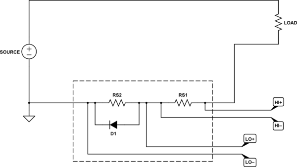
As for the wide range current measurement the following circuit can be an option:

simulate this circuit – Schematic created using CircuitLab
The shunt resistors, RS1 and RS2, should be selected for the current measurement range and the full-scale voltages. For the circuit above, RS2 >> RS1 (e.g. 100 Ω vs 10 mΩ). RS1 and RS2 should have adequate tolerance.
At lower currents, the voltage across RS2 is low enough such that D1 does not conduct, but also high enough so it can be measured with good precision. At higher currents, RS2 will be shunted by D1 but the voltage across RS1 can be used for current measurement.
The major downside of this circuit is that it requires multiple ADC channels. The other downside is that the load will no longer be grounded because of the present network.
Depending on the range requirements, the number of R-D pairs can be increased but so does the required number of ADC channels.
As far as i am aware(please correct me if i'm wrong) the possibly occuring low frequency, the sawtooth waveform as well as the wide frequency range excludes the use of current transducers or isolation transformers fully.
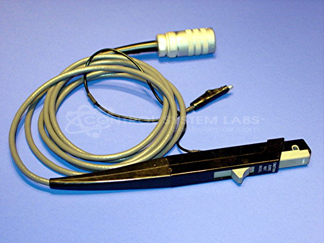
Yes, it does exclude normal transformers, but hall-effect sensors can be used to extend the low-frequency range of normal CTs down to DC, a technique that has been used for decades in test instruments, for example, the Tektronix A6302 series clamp-on current probes that plug into a scope to view waveforms, these could measure amplitudes up to 20A rms, with bandwidth from DC to 50MHz. But they cost several thousand dollars, so that's probably not going to suit.
Image source:
https://controlrepair.com/shop/tektronix-a6302-current-probe-49963
Recent developments in magnetic sensors have produced some sensors that will go very close to providing what you need. The bandwidth you need is no problem, however, to cover the wide amplitude range you have specified, you may need to stagger together 2 or 3 units of different sensitivity, and you will need to ensure the more sensitive units are well protected when the current exceeds their nominal range.
LEM is one OEM to look at. They produce a wide range of hall-effect and flux-gate current transducers, all with galvanic isolation. In the precision category, they have two ranges, "stand-alone", and "rack-mount". In the stand-alone series, the model IT 60-S will measure up to +/-60Adc, with a linearity better than 20ppm (parts-per-million) and a bandwidth from DC to over 800kHz.
In the "rack-mount" series, the ITZ 600-SPR will measure up to +/-600Adc, with a linearity better than 1ppm (parts-per-million) and a bandwidth from DC to over 500kHz.
This data was extracted from LEM publication titled "High Precision Current Transducers", refer pages 26 & 27, downloaded from this website:
https://www.lem.com/en/high-precision
These were just two examples I happened to find via a websearch, there are many others, from LEM and other OEMs.

