0
\$\begingroup\$

Good morning everyone,

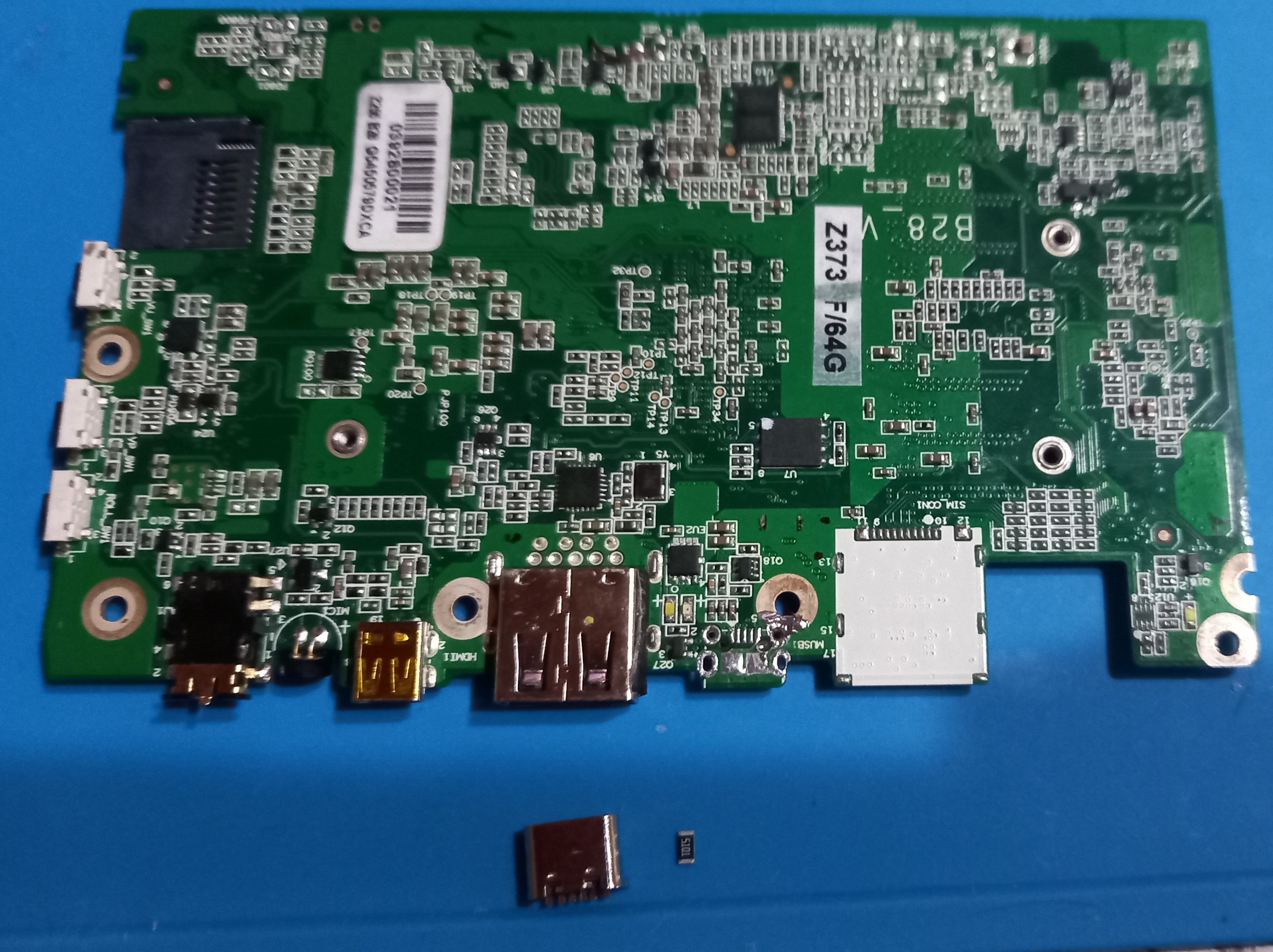
I received help from several members of this page regarding my goal of adding a USB-C connector to a tablet that already has a micro USB connector for charging. After researching mux configurations and diode OR-ing, I realized that the voltage drop would be too significant due to the forward voltage drop (Vf) of the diodes. Therefore, I decided to simplify things and follow the recommendations to connect both receptacles (USB-C and micro USB) in parallel.

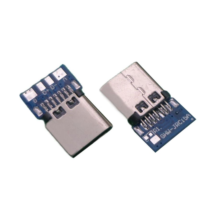
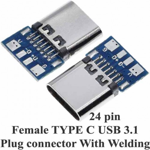
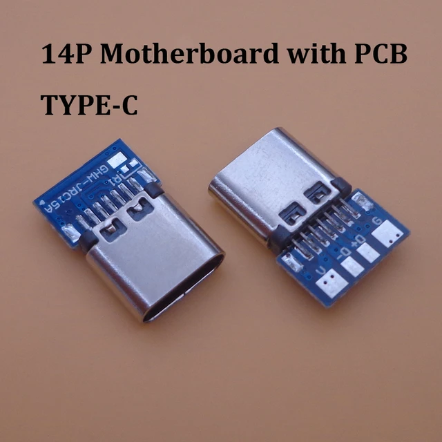
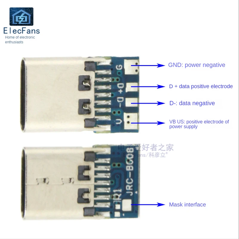
Upon closely examining the USB-C module, I noticed that it does not have pull-down resistors built into the CC pins. According to the information I have gathered, it is a USB-C connector (with 7 pins on each side) that includes ground, data, and voltage markings, but I am unsure if it has the configuration pins (CC) for connecting the resistors.

Another concern is whether, when connecting the two connectors in parallel, I need to include the pull-down resistors on the CC pins of the USB-C receptacle and the short-circuit resistor in the micro USB receptacle (using the old BC protocol). I don't want to leave those connections floating.

Thanks for all the help. Greetings to all!

P.S.: Apologies for any grammatical errors in my English; I am still learning the language.

enter image description here

enter image description here

enter image description here

enter image description here

enter image description here

enter image description here

enter image description here

\$\endgroup\$
1
  • 1
    \$\begingroup\$ I can't see where anyone recommended to put the two connectors in parallel. I recall reading it might be possible but not a good idea. It definitely is not a good idea, and I would recommend specifically to not put two USB connectors in parallel. \$\endgroup\$
    – Justme
    Commented May 29 at 21:33

1 Answer 1

0
\$\begingroup\$

The problem is you are asking if it's possible. Yes it is, you seem to have done/decided it already. What you should have asked if it's technically or in any other way the correct solution, which is isn't.

Basically, if you ask me if you should replace MicroUSB with Type-C, or add a Type-C in parallel with MicroUSB, my question is, have you really thought all the details and aspects if it is feasible in your case, and even then, is it really worth the trouble for what you gain or lose by adding the Type-C and want to do it so that the tablet remains safe and usable, especially if it is old and not yours, as it may get damaged in the process.

If your Type-C has no resistors on CC pins, it can't work at all. No Type-C charger will detect anything being connected and will not output 5V. Except if you use a cable with a Type-A plug and Type-C plug which are allowed to output 5V from the Type-C plug without asking.

The problem is, the MicroUSB is likely an OTG port which can be host that supplies power or device that uses power for charging, and can detect battery charging BC protocol.

So, if you do just pull down the CC pins with a resistor, it means your device is only a device that requests power, and can't support OTG. The Type-C without USB data wires can't detect BC protocol charger, and it can't detect Type-C available current as you have no electronics on CC pin and it sure won't communicate how much current is available via USB PD either.

So for the Type-C connector to be able to negotiate with a BC port, you need to connect the USB data pins too.

That might work fine for both ports to detect the BC signaling, which is quite low speed. I think Type-C chargers are required to support BC so it might actually work.

But now you have paralleled two receptacles with power and data wiring.

The USB data lines can work at speeds up to 480 Mbps. The data transmission requires a clean transmission line with specified characteristic impedance. Paralleling two high speed data connectors even properly is not possible due to the branching causing impedance mismatch and signal reflections, let alone if done with random airwiring between receptacles. What you likely experience is that data transfer through either USB connector is either impossible or limited to slow 12 Mbps speeds, or working intermittently, so that there are errors before you can transfer what you needed to transfer.

The second problem is the two connectors being paralleled for power connections. It allows to connect two power supplies, or two computers, or one power supply and one computer, and other combinations of two devices never intended to be connected together. Power supplies or PCs may damage if you short circuit their outputs.

What's worse is that if you plug in a MicroUSB supply, you have same 5V VBUS on Type-C receptacle without negotiation, which is not allowed and expected by any device that has a Type-C plug.

Same applies when Type-C charger is connected - the MicroUSB will output 5V even if not requested by OTG adapter via ID pin.

One more quirk you need to be aware of is that as the Type-C plugs are flippable, your receptacle needs to handle not one buy two CC pins, and no you cannot parallel them or active/e-marked cables will not work. Your receptacle also needs to handle two sets of USB data pins, which actually need to be paralleled. Unless your breakout board already does these for you.

\$\endgroup\$
4
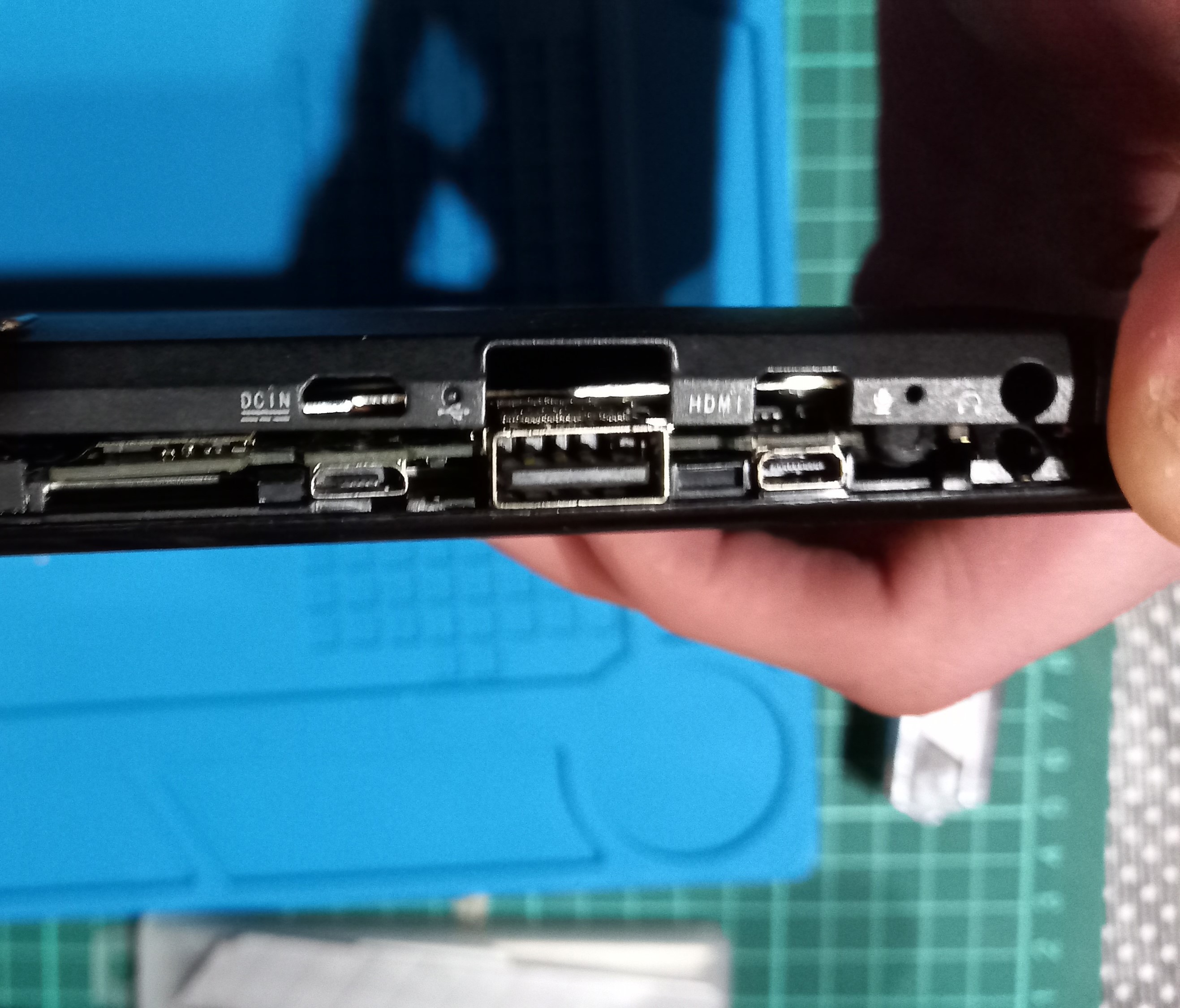
  • \$\begingroup\$ Hello. Thanks for responding and for all the information. Regarding your answer, it does not look like an OTG port. In fact, I tested it before disassembling it, and it is only a charging port (with an OTG port, I would not dare to do what I have in mind). If you see the symbol written on the case, it is the direct current indicator (I have uploaded photos (DCIN)) \$\endgroup\$
    – condor12
    Commented May 30 at 7:20
  • \$\begingroup\$ In this case, since the pins are odd, some sources say the module has 14 pins, while others say it has 24 (I have uploaded photos). I have seen the copper vias on the PCB, and as you mentioned and as I suspected, it cannot work without the CC pins connected. So, I need to add them somewhere. However, I am not sure where to solder the CC pins on the USB-C module. You are right about the parallel connection and the problem with the different connector types and the 5V. Do you have any recommendations on how to handle this situation? \$\endgroup\$
    – condor12
    Commented May 30 at 7:20
  • \$\begingroup\$ @condor12 Shops where you bought the connector don't always understand what they are selling - Yes the connector has 24 pins, with 14 pins to the PCB, and from there you get 5 pins to 5 wires - without proper description what the "Mask Interface" is supposed to be in English. You also link to several different boards, so unknown which you have. If you ask for a recommendation, the best way to handle the situation would be to not be in the situation to begin with. Just leave the MicroUSB and forget Type-C would be my recommendation, and you will have an usable tablet. \$\endgroup\$
    – Justme
    Commented May 30 at 8:26
  • \$\begingroup\$ Is it really that difficult to put this into practice? I wanted to experiment with an old tablet first and then apply it to newer devices. Thanks for clarifying the number of pins for me. As you mentioned before, and as I suspect, it is not possible to use the connector without connecting the CC pins. Could you tell me where these pins are connected in these modules? You've said that it's possible to do what I have in mind, so could you enlighten me a little? Maybe you could give me some clues. Regarding the USB-C module, how many pins does it actually have? Thank you. \$\endgroup\$
    – condor12
    Commented May 30 at 18:32

Your Answer

By clicking “Post Your Answer”, you agree to our terms of service and acknowledge you have read our privacy policy.

Not the answer you're looking for? Browse other questions tagged or ask your own question.