2
\$\begingroup\$

When running at a fast signal, why does the MOSFET below not turn off, even when gate voltage is well below threshold (even negative)? Although the signal is fast (7 MHz, 140 ns period) it is < 1/10th the turn on / turn off time.

enter image description here

For that matter, it doesn't seem to fully turn on either.

The datasheet shows gate threshold voltage to be between 0.8V and 3V. The troughs are well below 0.8V, and the peaks above 3V. Furthermore, increasing amplitude to 4V (so that gate voltage goes from -4V to 4V) didn't substantially change things: we still see R1 current between 0.93mA and 1.26mA, and drain voltage never above 2.4V.

The cause can't be attributed to input capacitance, as the input is an ideal voltage source.

Decreasing the frequency to 1 MHz solves the problem: enter image description here

But why? The datasheet shows turn off and turn on times of 10 ns, well within the 140 ns period of Vsig. Why does the MOSFET fail for fast signals, even if their period is > 10x turn off and turn on time?

\$\endgroup\$
9
  • 1
    \$\begingroup\$ The cause can't be attributed to input capacitance, as the input is an ideal voltage source. What about Cgd? \$\endgroup\$
    – John D
    Commented Jul 10 at 19:55
  • \$\begingroup\$ @JohnD Could you elaborate? Or perhaps post a full answer? \$\endgroup\$ Commented Jul 10 at 20:03
  • \$\begingroup\$ Where did you get the BS170 model? \$\endgroup\$
    – rohmeooo
    Commented Jul 10 at 20:47
  • \$\begingroup\$ @rohmeooo From ltwiki.org/?title=Components_Library_and_Circuits . I tried a few other random MOSFET models and got similar results. \$\endgroup\$ Commented Jul 10 at 21:02
  • \$\begingroup\$ Did you check the capacitances in the datasheet? Perhaps you need the definition for Coss, Crss, etc. \$\endgroup\$ Commented Jul 10 at 23:08

1 Answer 1

2
\$\begingroup\$

While you may not have drawn a resistor in series with V2, the mosfet model most certainly contains one.

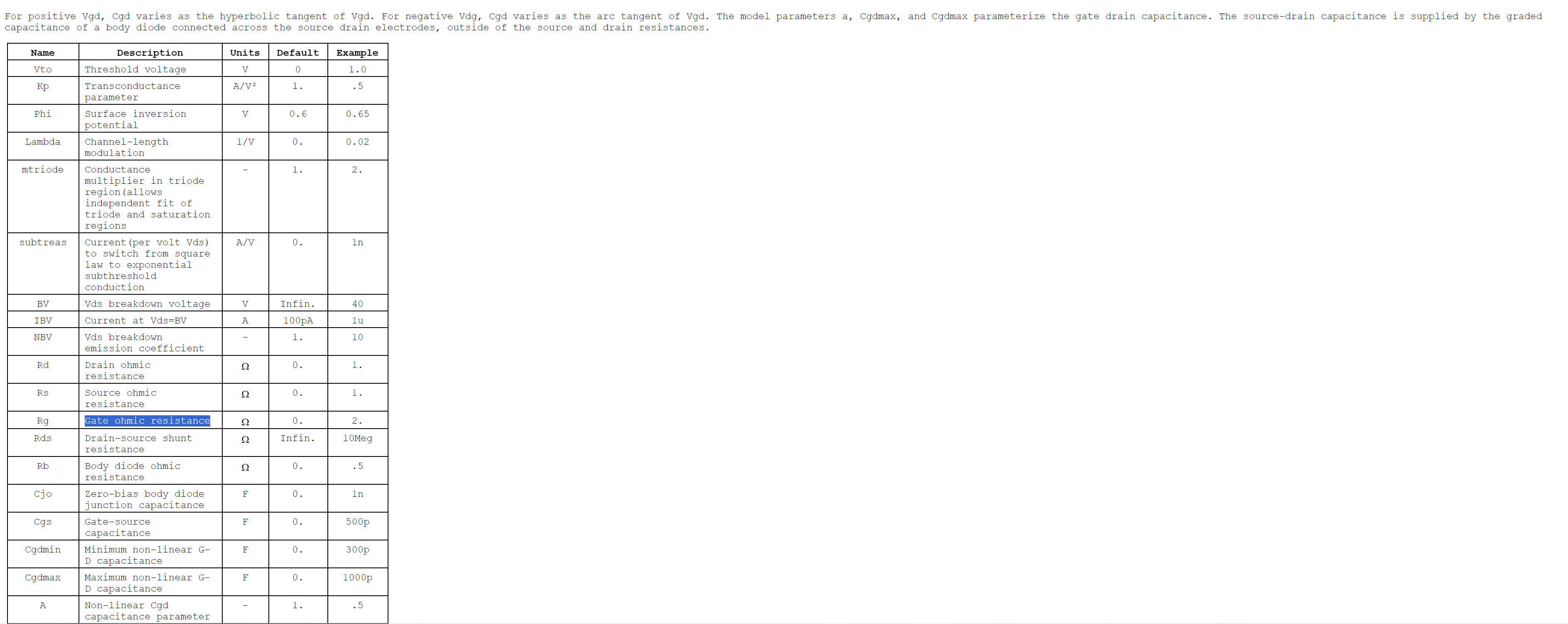
See LTSPICE wiki: https://ltwiki.org/LTspiceHelp/LTspiceHelp/M_MOSFET.htm which in the table contains an R_g parameter as seen in this snippet: snippet of LTwiki mosfet page

While your model could have a 0 ohm resistance, I posit that it doesn't because of the behavior you are showcasing.

I suggest you inspect the model, find the gate resistance, set it to zero, then place a discrete gate resistor, and observe gate voltage again. Then you will see the effect of the capacitances.

Or, just observe the current out of V2 and you should see the unmistakable current caused by the input capacitance and, more notably, the miller capacitance.

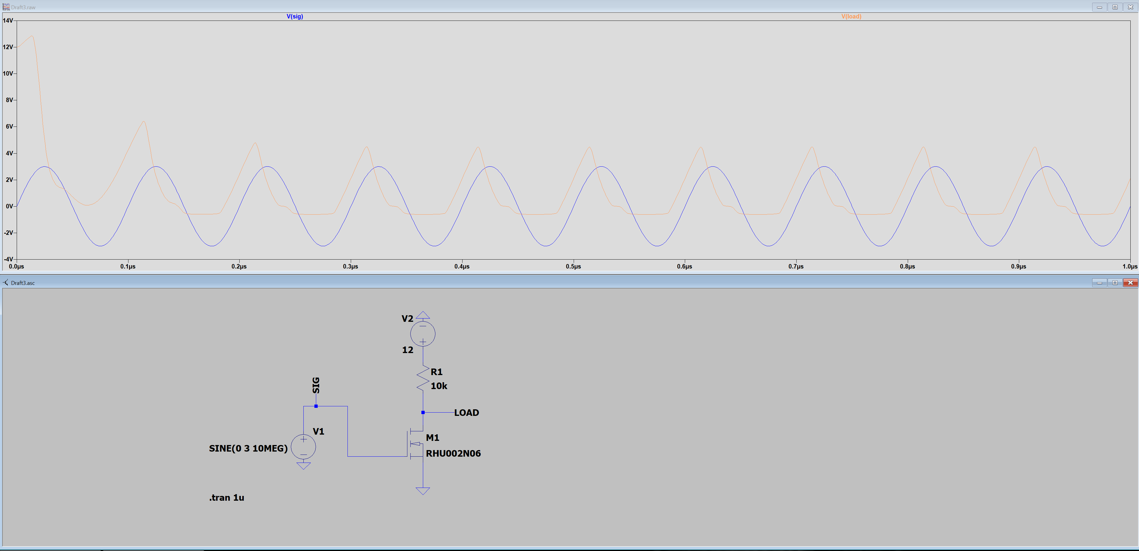
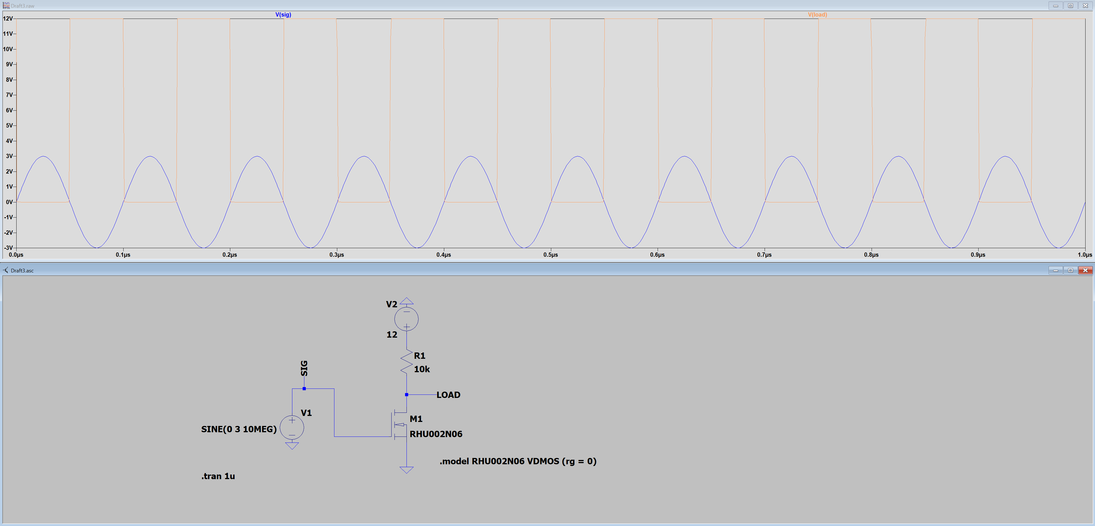
For instance, I grabbed a random model and put a 10MHz sinewave through it, just as you did.

See my results with the model, as supplied, and one where I over-write the gate resistance to 0 using a .model statement: First: mosfet model as supplied. using mosfet model as supplied Second: mosfet model with gate resistance set to zero. using mosfet model with gate resistance set to zero

\$\endgroup\$

Your Answer

By clicking “Post Your Answer”, you agree to our terms of service and acknowledge you have read our privacy policy.

Not the answer you're looking for? Browse other questions tagged or ask your own question.