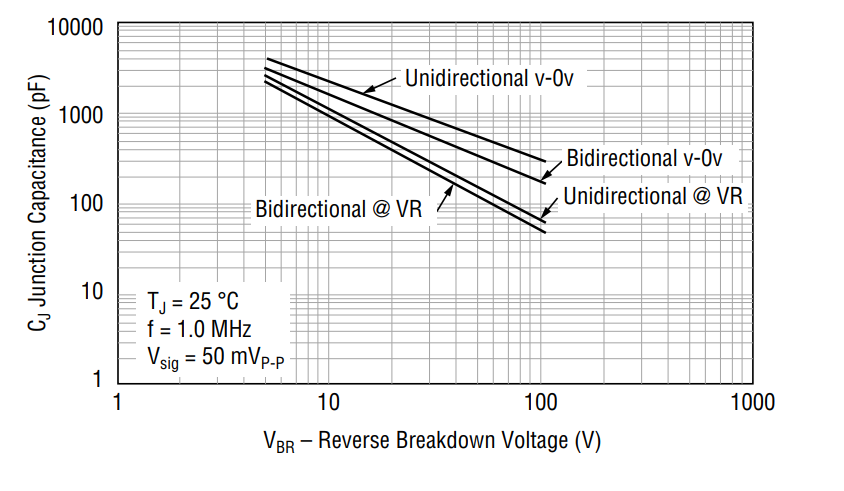
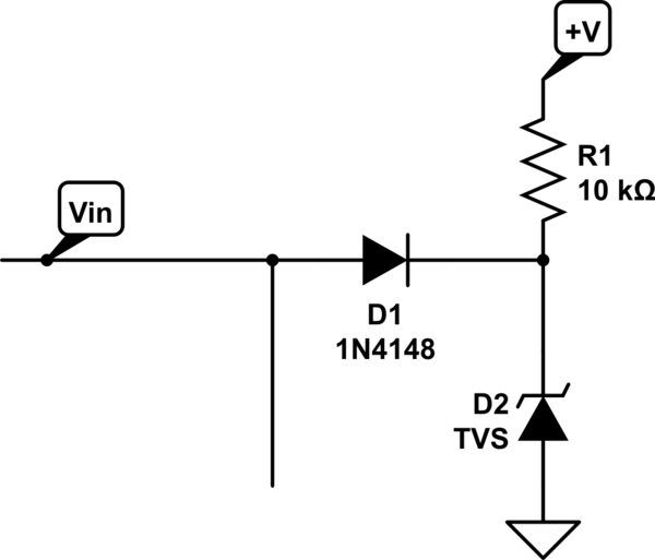
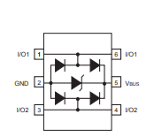
I hope you are fine. I have a question. I have generated a 4Vpp signal with a 5MHz frequency using the following sequence: AD9851 (DDS) → AD8001 (Op Amp) → Ferrite bead (2KΩ) → Microfluidic sensor This signal is connected to a microfluidic device whose impedance varies from 3KΩ to 10KΩ. When I attach any through-hole TVS diode with a Reverse Stand-Off Voltage (V_R) rating of 6V to 30V across the signal, with one pin grounded and the other pin across the signal for circuit protection, it drops the signal to less than 1Vpp. My questions are:
- Why does my signal amplitude drop significantly, even though the Reverse Stand-Off Voltage (V_R) is much higher than the signal amplitude?
- I want to match the impedance between my microfluidic device, which has an impedance ranging from 3KΩ to 10KΩ, and my signal, which currently has an impedance of 50Ω without the ferrite bead (2KΩ). a) How can I increase the impedance of the signal? b) When I add some series resistance across the signal, it greatly reduces the amplitude. Please suggest a solution to match the signal impedance with the microfluidic impedance without dropping the signal amplitude. C) does connecting a ferrite bead of 2KΩ in series to the signal add to the overall impedance of the signal? The AD8001 has high input impedance and low output impedance, making it perfect for this application. Your response would be highly appreciated.


