You wouldn't usually use zener diodes for a task like this, nor would you use them in series. Zener diodes are used for voltage clamping and they're not particularly suitable for regulation outside specialised cases. You really just need a regulator.
The current is really what's going to matter here in terms of your choices. If it's a low power MCU, you can probably just use a linear regulator. If it's a higher power MCU, you might need a switching regulator.
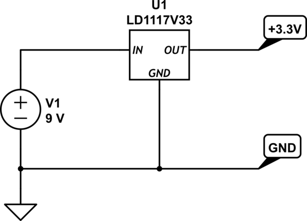
Using a linear regulator is pretty easy. The usually come in 3-pin packages, and you hook them up as follows:

simulate this circuit – Schematic created using CircuitLab
Linear regulators dissipate power proportional to the voltage differential and the current, i.e. \$P_D = (V_{in}-V_{out}) \times I\$. If you look at some linear regulator datasheets, you'll find specifications for the thermal resistance between the junction (the silicon inside the device) and ambient air, usually denoted \$\theta_{JA}\$ or \$T_{JA}\$, in °C/W or K/W (they're the same thing). This tells you the expected temperature increase of the junction as a result of a particular power dissipation, if the device is just standing in air with no heatsink or forced air cooling. Make sure you check that you're reading the number for the correct package, as some parts are available in different packages (e.g. TO-220, SOT23, TO-263, etc.) and the thermal properties differ between them.
For example, let's say your microcontroller has a peak current draw of 100mA. The max input voltage is 9V, and your output voltage is 3.3V. This gives us a power dissipation of \$(9\text{V}-3.3\text{V}) \times 0.1\text{A} = 0.57\text{W}\$. If you went with a Texas Instruments LM1117-3.3 regulator in a TO-263 package, it has a thermal resistance of 41.3°C/W. Since we're dissipating 570mW, that means a temperature rise of \$0.57\text{W} \times 41.3\text{°C/W} = 23.54\text{°C}\$. If we assume a max ambient temperature of 35°C, that means your junction temperature should end up being about 60°C. The datasheet says the max junction temperature is 125°C, so you're fine. Usually you want to keep it below 100°C for safety.
However, let's say you've got a more powerful MCU (e.g. an ESP32) with some peripheral ICs that also draw some current, bringing you up to 500mA. Running the calculations again, the power dissipation jumps up to 2.85W. This results in a temperature rise of 118°C, putting your worst case junction temperature up at 153°C, which exceeds the maximum for that part. Switching to the TO-220 package version drops the thermal resistance to 23.8°C/W, reducing the worst-case temperature to 103°C, which is manageable but still pretty excessive.
The other problem with using linear regulators in battery powered scenarios is wasted power. You'll notice the linear regulators burn a lot of power as heat, as mentioned above. That power is coming from your battery, so it will drain fast. Put simply: the efficiency of the regulator is the output voltage divided by the input voltage, so in your case less than 37% efficient, meaning 63% of your battery's energy is being wasted.
To get around this problem we usually use switching regulators. These are far more efficient - capable of achieving over 90% efficiency - but they are more complicated. Luckily for you, you don't need to know much about the internals of them in order to use one in such a simple scenario. You can buy premade 3-pin switching regulators that are designed to be more efficient substitutes for linear regulators. You just need to make sure to select one with a minimum input voltage around 7V or less, and a maximum input voltage over 9V.

