0
\$\begingroup\$

Well, I am cranking my head around this one. I have a 5V microcontroller (AtTiny2313a-pu) which drives a 12V(max) DC motor(ampere rating unknown).

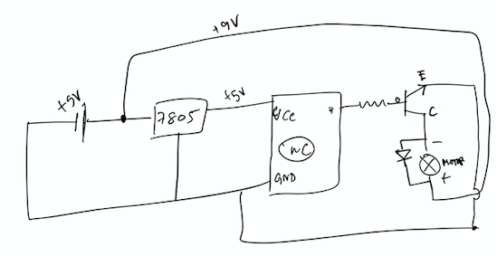
I have programmed my uC correctly and caused the motor to "blink" for one second then turn off for one second and so on(not resorting to PWM). I tested using this using this schematic and it works. (I am using a TIP120 npn transistor)

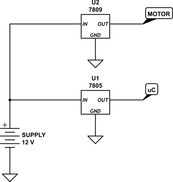
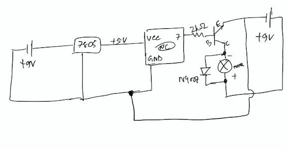
enter image description here Instead of using two batteries/ supplies, I tried to use the same battery for powering my microcontroller and Load and I am getting very strange behavior. I set the blink time to 2sec but here with this schematic(below), I observe random switching. enter image description here

I have read about a phenomenon called ground bounce from the noise generated by motor that is temporarily resetting my microcontroller.

I followed the instruction from a similar post that appeared in the forum and I tried to connect the battery ground to collector first then to my microcontroller and its regulator as mentioned in the answer but I observe the same strange behavior of resetting. How would I get rid of this behavior?

Also, I have a 12V 2amps adapter and I want to power my project through this. Is there a way to split 12V into 5V(for microcontroller) and 9V for Motor as an independent power source as described in schematic 1?

I read that linear voltage regulators are very bad for powering motors,Will buck converter serve my purpose?

PS: I am very new to electronics please don't vote me down. In case I miss something I will modify in the post and abide by the standards of this forum.

Thanks you

\$\endgroup\$
12
  • 2
    \$\begingroup\$ Did you know your transistor is backwards? \$\endgroup\$ Commented Jul 7, 2020 at 10:45
  • 1
    \$\begingroup\$ Given the 9 V for the motor and a 12 V power supply, a "bridged" arrangement is indicated if you are interested in reversible motion. Look that idea up. If not, bridging isn't needed and you can develop a simple 9 V rail (see following re: 5 V.) And yes, you can also develop 5 V from the 12 V either with a "linear" (wasteful, but easy) regulator (7805, for example) or also a buck switcher (efficient and relatively cheap these days prebuilt.) Also, you need to learn how to use BJTs better. \$\endgroup\$
    – jonk
    Commented Jul 7, 2020 at 10:52
  • 1
    \$\begingroup\$ I'm sleeping, or is add more. ;) \$\endgroup\$
    – jonk
    Commented Jul 7, 2020 at 10:58
  • 1
    \$\begingroup\$ Probably you can use a linear for the 5 V if the wasted dissipation is tolerable. A motor usually requires more work. For one, it is often inductive and needs special attention for that. For another, if the motor isn't a toy, then it requires a fair bit of current. Does the motor require significantly less than the 24 watts you have available? Finally, a tip120 is a Darlington. Which often makes me cringe, unless you clearly understand why you are using that configuration. \$\endgroup\$
    – jonk
    Commented Jul 7, 2020 at 11:08
  • 1
    \$\begingroup\$ Please don't draw your schematics upside down. \$\endgroup\$
    – user16324
    Commented Jul 7, 2020 at 13:26

3 Answers 3

2
\$\begingroup\$

"But is it possible to make two supplies from the 12V 2amps adapter so that schematic 1 like circuit may fix this issue?"

Without knowing the current draw of the motor, the answer is, "Maybe, maybe not." It all depends on how much current the motor draws, especially on turn-on.

Presumably you are interested in trying something like

schematic

simulate this circuit – Schematic created using CircuitLab

Here's the problem: when motors turn on, they draw much more current than normal. As the motor starts turning and gets up to speed, the current required gradually drops to normal. When this happens, it will cause the output of the power supply to drop, and this will cause the uC voltage to drop - and you get weird behavior as the uC briefly stops working correctly.

You might think that the solution would be to put a big capacitor on the output of the 7805, to provide voltage for a brief period when there is a drop in the supply voltage. Unfortunately, that's not a good idea - 7805s don't like big capacitors on their output and may start oscillating.

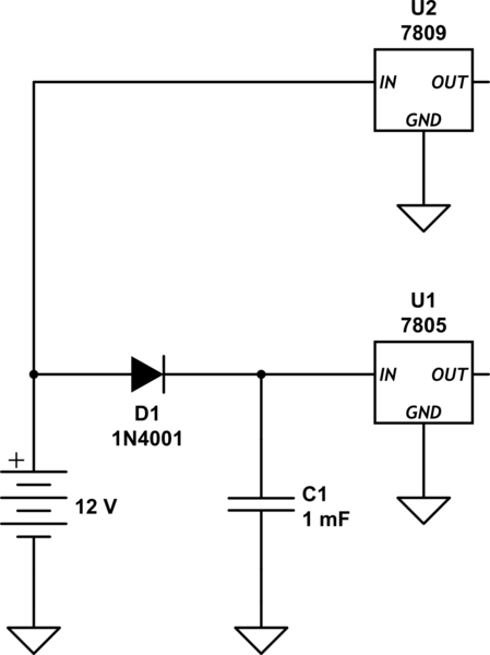
Instead, you should try something like

schematic

simulate this circuit

There are a few caveats.

1 - I have no idea how much current your uC circuit draws, so the value of C1 is entirely speculative. 1000 uF may be higher than you need, or it may be lower. It depends on how much current the uC draws, and how long a dropout you need to operate through.

2 - When power is turned on, D1 has to provide a high-current spike to charge up C1. Depending on what value of C1 you have, and how gradually the power supply turns on, it's possible that turn-on will blow up D1. In that case you would need a beefier diode.

3 - (optional) It's a good idea to start working with less obsolete chips. Learn to use something like an LM317 if you're willing to stick with linear regulators. At the expense of a couple more resistors, you can use a single part number for different voltages - and the performance of newer regulators is better than ancient, first-generation devices like the 7800 series.

\$\endgroup\$
5
  • \$\begingroup\$ Well i was seeing some specs of dc motors that look like mine and the current rating is around 300 to 500mA , what value of the large cap shall I choose? Btw will I have to in addition to this large cap of 1mF , add the caps suggested in datasheet of 7805? Can 7809 source enough current to turn the motor on ?(as i have seen experimentally 7805 actually was unable to provide the current to start the motor on? \$\endgroup\$ Commented Jul 7, 2020 at 14:50
  • 1
    \$\begingroup\$ @ArghaChakraborty - You should assume a starting current of about 10 times the running current. If you really have 1/2 amp motor, then starting current will be about 5 amps, or maybe even more for very short periods of time. A 7809 will not provide this. Your 2 amp supply will not provide this, either, and it's the source of your troubles. Basically, you need a much larger power supply. And PLEASE pay attention - there is nothing magic about 1000 uF. I just used that as a starting point. With more information it's possible to do detailed calculations, but not here. \$\endgroup\$ Commented Jul 7, 2020 at 15:09
  • \$\begingroup\$ But @WhatRoughBeast my motor turns on fine with even a 9v battery and with the 12v supply as well. Shall we assume a lower current rating like 200mA.? \$\endgroup\$ Commented Jul 7, 2020 at 15:12
  • \$\begingroup\$ Well actually this idea works . Previously I was trying to plug in large caps at the 7805 output hoping that it's will account for the transient voltage drop . After your suggestions I tried to plug 3mF cap on input and it works fine with both 12 volt 2 amp supply and my 9v battery as well. \$\endgroup\$ Commented Jul 7, 2020 at 19:44
  • \$\begingroup\$ @ArghaChakraborty - "Shall we assume a lower current rating like 200mA.? " No. What is the concern is not the steady-state current, but the peak current required to get the motor turning quickly. Batteries can take a high temporary load current, which gets the motor going, and then recover to provide running current. So, apparently, will you 12 V supply. I would add that it's entirely possible that the 12-volt supply has a largish capacitor on its output in order to cut down on noise and provide better transient response, \$\endgroup\$ Commented Jul 8, 2020 at 1:41
1
\$\begingroup\$

Your diagrams show no capacitors on the input or output of the 7805. So it may not be working correctly. Follow the recommendation in the manufacturer's datasheet. Adding them may be enough to solve your problem.

Motors take a large current surge on start-up. How large that surge is depends on the design of the motor and what load it is driving. This can make the supply voltage drop when you try to start it. A normal 9V battery may not cope with the extra current. If using a 12V power supply, again you need to know if the current output of the power supply is enough to handle the motor surge. If you have a datasheet for the motor, see if it lists a stall current.

PS. Your diagram would be a lot clearer if you drew the motor above the transistor. And drew the transistor with the terminals labelled correctly!

\$\endgroup\$
1
  • \$\begingroup\$ Unfortunately, the datasheet for the motor is not provided? I will add the caps at the entry and exit of my linear regulator and check. But is it possible to make two supplies from the 12V 2amps adapter so that schematic 1 like circuit may fix this issue? PS:I have edited the schematic \$\endgroup\$ Commented Jul 7, 2020 at 11:08
1
\$\begingroup\$

You can't power this circuit from two independent (isolated) power supplies. You must have a common ground for this circuit to function, and once you have the grounds of two different power supplies connected, it is no different and no more independent than what you already have.

The TIP120 only turns on if there is current flowing through the base and out the emitter. For current to flow, the base voltage must share a common ground with the motor drive voltage.

To use two isolated power supplies would require something like an opto-isolator between your ATTiny and the transistor base.

Different voltage potentials with a common ground are, well, different voltage potentials with common ground. There is nothing you will gain (and indeed, it will be functionally equivalent) by any circuit you might use to derive two different voltages from a single power supply.

So yes, you can split your 12V power supply into a 9V and a 5V power supply. You would do so by using an LM7805 and LM7809.

The only way would require creating an isolated voltage source using something like a flyback converter and a transformer, but this is far more advanced than is even reasonable to build for something like this.

I promise you that your problem has nothing to do with how you're getting the 5V rail from a single power source, and has everything to do with your complete lack of any capacitance anywhere. You don't even have a ceramic capacitor for your microcontroller.

When the motor turns on, it causes a voltage sag that drives the 7805 out of regulation (the voltage drops briefly) and this triggers the brown-out detection on the ATTiny, causing it to reset itself. Additionally, the 7805 isn't even stable without input and output capacitance in the first place, so I'm amazed the circuit worked at all.

Either way, whether it is with a 9V battery or a 12V power brick, you need some bulk capacitance there to handle the large current spikes switching on the motor will demand.

That will be far far easier than any possible way to generate an isolated output from an existing power supply.

But if you really want two power supplies... just power the motor from the 12V power brick and power the microcontroller and the 7805 from a 9V battery, with their grounds joined. Batteries work as isolated power supplies in a pinch, albeit ones with limited capacity.

Another note: There is no point in powering the motor from a 12V power supply, at least with the circuit as you have it now. The TIP120 is an NPN darlington transistor, yet you're using it as a high-side switch. For base current to flow out of the emitter, the voltage at the emitter must be less than the base voltage minus 0.7V for the base voltage drop. This means you won't ever be able to turn on the transistor more than a few volts (or less) at the emitter, and that is the most the motor will see. The rest of the 12V will be dropped across the transistor, making it get very hot very fast.

You need to use NPN transistors as low-side switches. Connect the collector the motor's negative lead, and connect the emitter to ground. This will let you properly power the motor from 12V.

Final note: motors are noisy. The pull-up on the reset pin on AVRs is usually pretty weak and it is possible that noise could couple in and trigger a spurious reset. You should consider using a stronger external pull-up resistor, like 10kΩ to VCC on the reset pin (pin 1).
\$\endgroup\$
2
  • \$\begingroup\$ Well I have common ground in schematic 1 if you observe but I know the schematic drawing skill should be improved. Will a 7809 source enough current to power the motor if the motor rating is at around 500mA .? The problem is I dont have the datasheet of the motor or its part no ,so i googled for datasheet of similar looking motor whose avg current rating ranges from 200mA to .8A. Can you provide a schematic for using darlington as low side switch? Thanks for you suggestions . \$\endgroup\$ Commented Jul 7, 2020 at 15:06
  • \$\begingroup\$ Load reg current of a 7809 is ranging from 5mA to 1.5A, from the datasheet static1.squarespace.com/static/5416a926e4b09de8832655bc/t/… \$\endgroup\$ Commented Jul 7, 2020 at 15:25

Your Answer

By clicking “Post Your Answer”, you agree to our terms of service and acknowledge you have read our privacy policy.

Not the answer you're looking for? Browse other questions tagged or ask your own question.