1
\$\begingroup\$

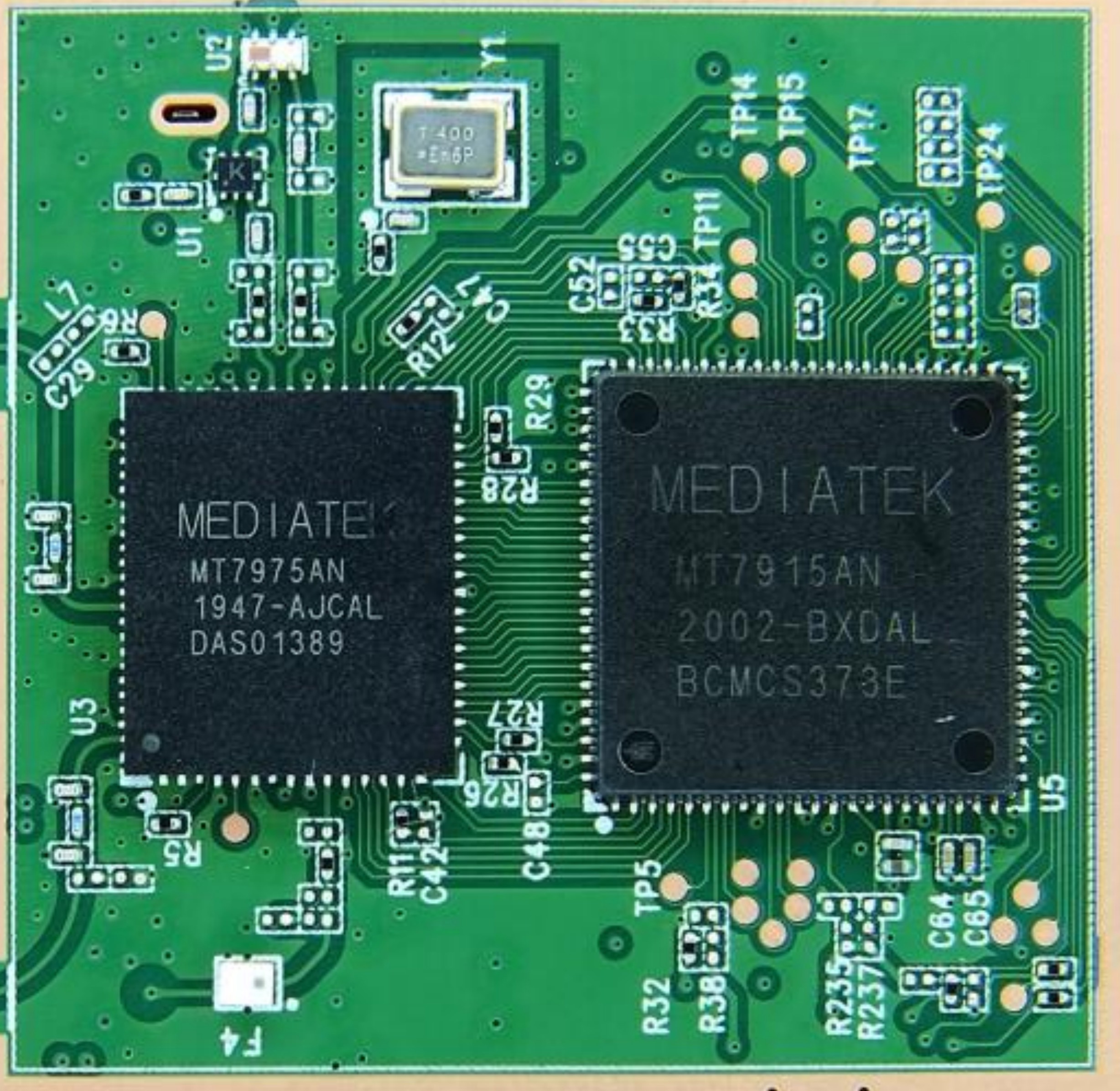
I'm troubleshooting a router that is missing WiFi and I figured out it's not seeing MT7915 on PCI bus. The router is using MT7975 (RF frontend) + MT7915 (WiFi) combo. I've started checking usual stuff like power rails, enable signals and clocks. 40MHz clock is missing on both chips so it's likely my issue.

However when I checked XTAL circuit I was surprised to see a standard SMD 2520 XTAL but it's connected in a way that makes no sense to me. XTAL input (pin 1) is connected to MT7975 and all 3 other pins are grounded. The XTAL Out pin from MT7975 connects to clock input pin on MT7915 so I assume both chips share the same clock.

How is it supposed to work when XTAL's output is connected to ground?

I've attached photos from 2 different devices using the same combination of chips and the same XTAL circuit.

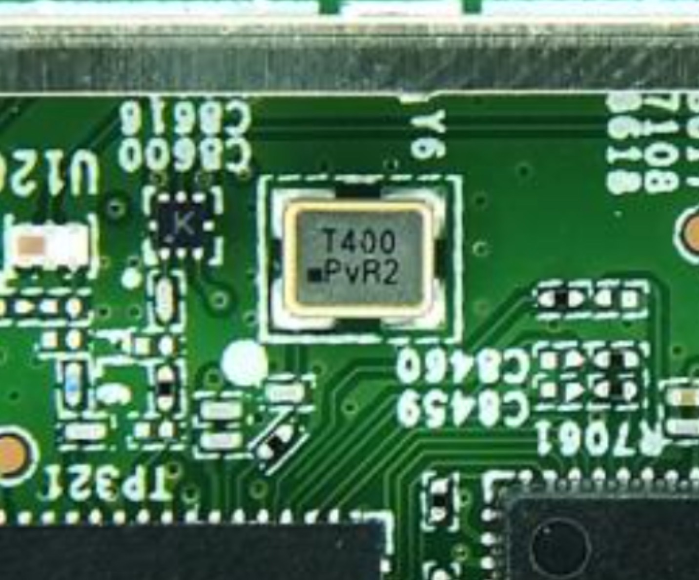
XTAL circuit
enter image description here

\$\endgroup\$
2
  • 1
    \$\begingroup\$ "and all 3 other pins are grounded" Have you measured that these pins are connected to ground, or did you only visually inspect the PCB? \$\endgroup\$
    – Velvet
    Commented Nov 1 at 10:27
  • 1
    \$\begingroup\$ Yes I measured it too. I also removed the XTAL and 3 out of 4 pins are definitely grounded. I have no idea how it's supposed to work. This is the first time I'm seeing it. \$\endgroup\$
    – DoubleJ
    Commented Nov 2 at 11:25

1 Answer 1

0
\$\begingroup\$

On the last image, it looks like pin 3 (upper-right) has a via to the left of the pad, which I suspect is not connected to ground.

\$\endgroup\$

Your Answer

By clicking “Post Your Answer”, you agree to our terms of service and acknowledge you have read our privacy policy.

Not the answer you're looking for? Browse other questions tagged or ask your own question.