a friend of mine came to me with a question and I thought I'd ask you guys for some insight. They were wondering if it would be possible to speed up a regular wall clock so that it would cycle twice as fast as normal. It wouldn't need to be extremely accurate, but if it were accurate to within 10% (ie. one rotation of the second hand would be between 27 and 33 seconds) that would be nice. I think I have a basic idea of how regular quartz clocks work, but I'm really shaky on most of the details, so here were my two thoughts:
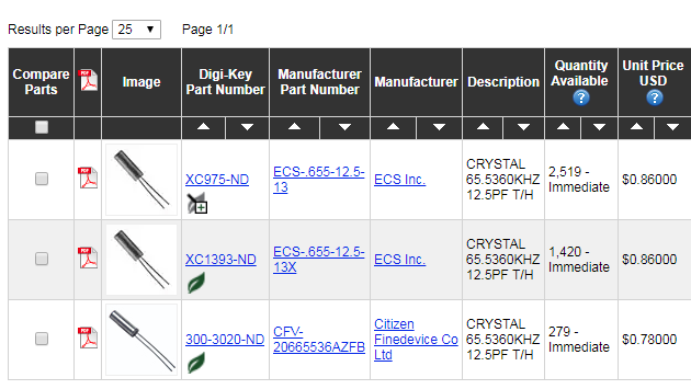
Inside a quartz clock, there will probably be a crystal soldered onto a PCB somewhere. If you could find a crystal with the same footprint and pinout that vibrates roughly twice as fast, popping off the old crystal and soldering the new one in would probably work. This would be really easy to do, but I see a few problems. For starters, finding a crystal that meets the listed requirements might be a challenge. Also, I'd imagine that at some point the crystal's vibration gets converted into a square wave. Since the conversion circuitry is based on vibrations, I'm guessing that this all happens within a single package, so you'd need to find a replacement which also has the same drive as the one you're replacing. If the conversion happens externally somehow, you'd still need to make sure that it will work properly with a crystal that's vibrating twice as fast and that its output is linear. I don't think this is the case though, because I'd imagine a "100kHz crystal oscillator" means a crystal with circuitry outputting a 100kHz square/sine wave rather than a crystal actually vibrating at 100kHz.
It might be possible to just yank out the entire crystal/oscillator and replace it with some external driver like a GPIO pin from a microcontroller. Assuming the oscillator's output is relatively slow (it looks like a common clock oscillator speed is 32kHz) and it's driving level isn't super different from a regular GPIO pin, you could just disconnect the oscillator entirely and solder a GPIO pin from something like an Arduino Micro to the pad where the oscillator used to be connected. Then you could drive the GPIO pin with the microcontroller's own oscillator/clock divider and just simulate a crystal. As far as I can tell, the main problem with this approach would be interfacing and making sure that the microcontroller's square wave roughly matches what the old oscillator was putting out
That's all I could really think of. I don't see any humongous, glaring oversights in either line of reasoning, but I thought I would ask you guys if I'm missing an obvious solution or if both of these are totally impossible. I plan on taking apart some analog clocks over the next few days and poking at them to see the characteristics of their oscillators, but I was hoping that somebody here would have a better idea than me of roughly how they work
Thanks

