0
\$\begingroup\$

I have a PCB that I am currently supplying 12V which has control of multiple contactors (12V coils with built in economizer so a set voltage should be all that is needed). The board closes all 5 contactors at start up after checking all is ok (300ms apart to allow for max pickup current time so that the higher driving loads do not overlap).

The issue I am having is that occassionaly on startup the board closes the first contactor and immediately opens (The sound is instant I just haven't checked on a scope as I don't have the product on hand just yet!). This opening is because the MCU resets. What is weird is that it does this once and maybe a second time but then it works absolutely fine then goes through the routine and closes all 5 contactors and keeps them closed with the rest of the PCB working perfectly from then on.

I was mainly just seeing if I am doing something or thinking of something obviously wrong? Mainly as I would normally expect an issue on opening contactors, not closing.

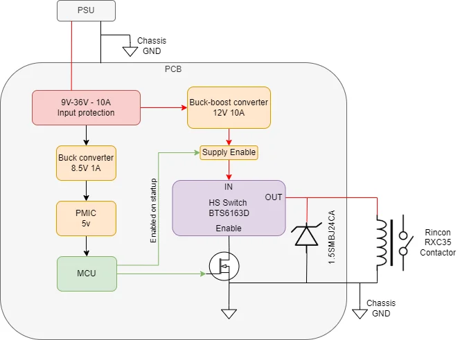
Here is a top level overview of what the PCB does, I can share schematics if more useful?

System Architecture

The only issue I can see is that the diode is on the PCB and the low side of the contactor is connected to chassis GND to could the path be going though that instead of the diode? Although, as mentioned I would expect an issue with opening and not closing.

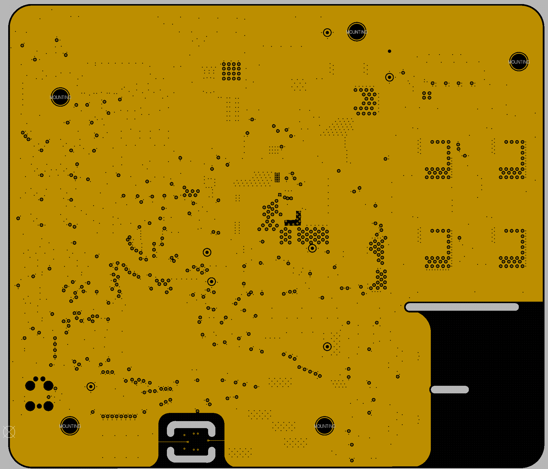
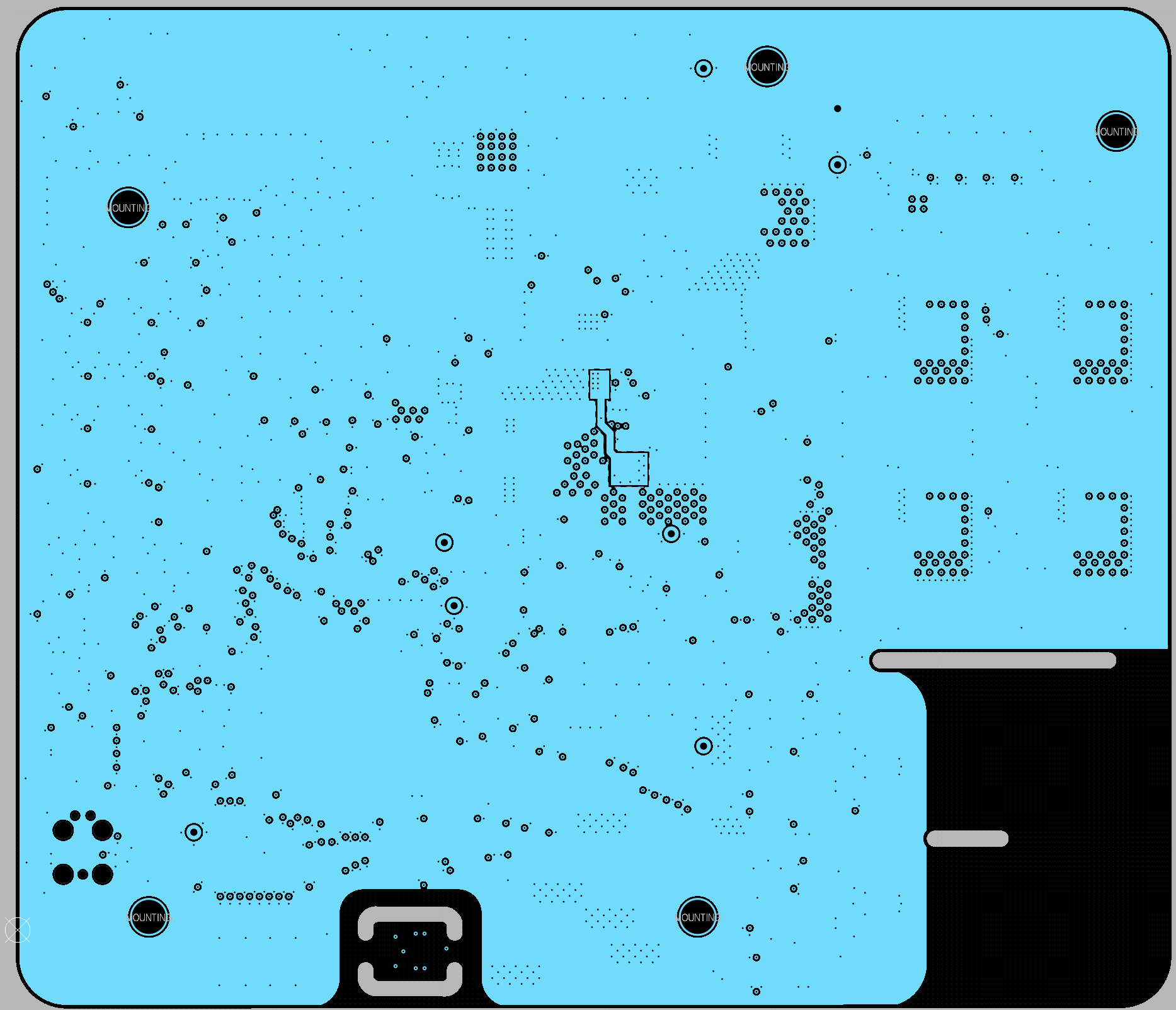
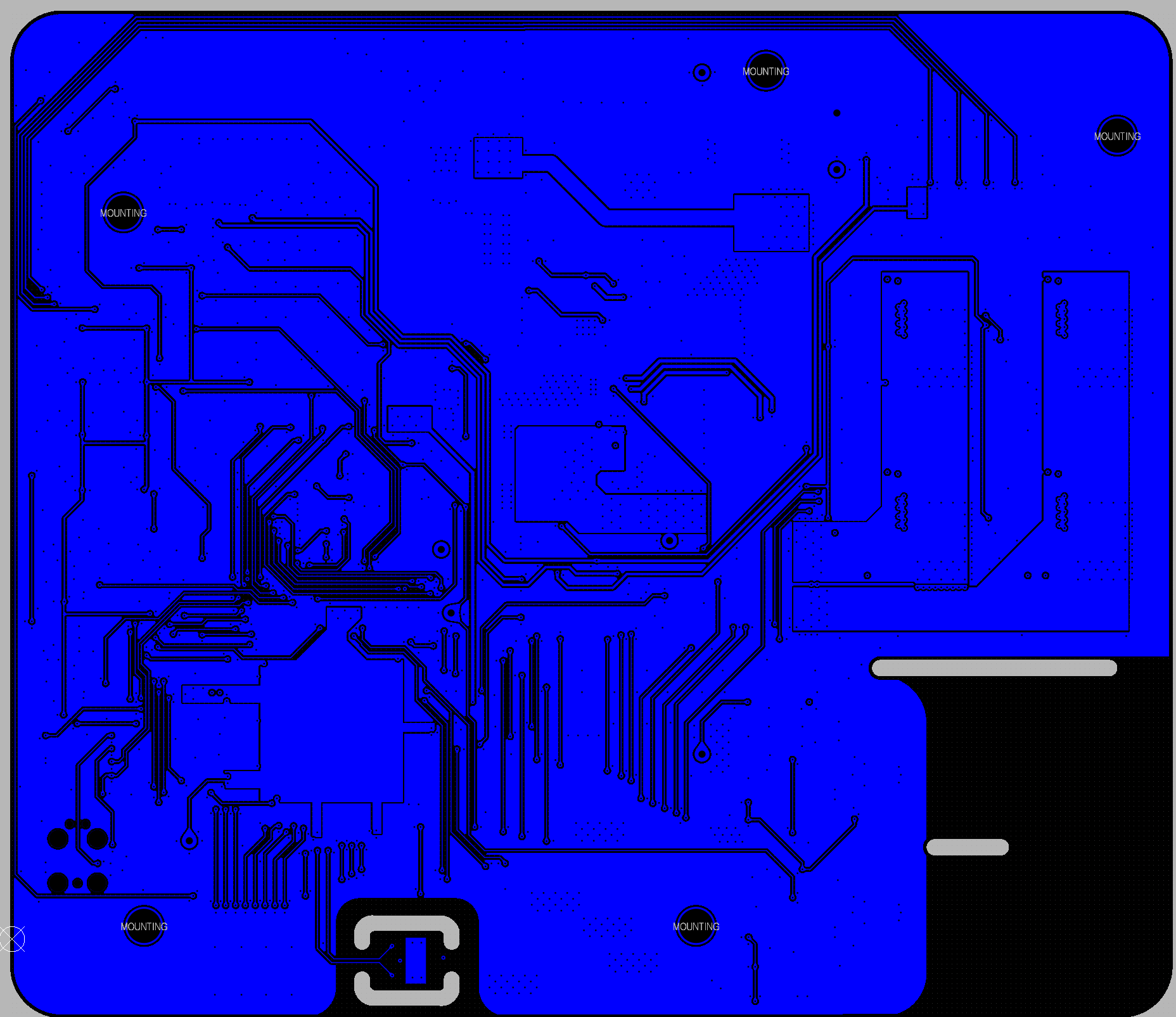
Maybe a ground loop issue as the whole PCB is on a shared GND plane that is solid on the 2 inner layers and stitched through to top and bottom as well, do I need to seperte this more?

Thanks in advance!

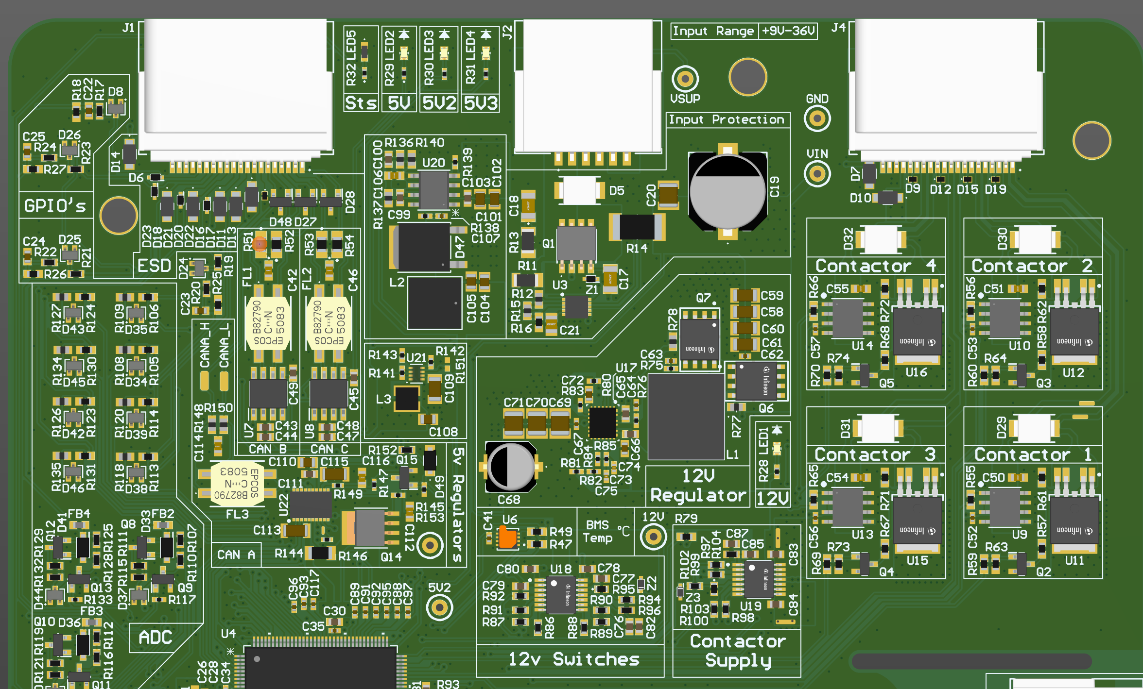
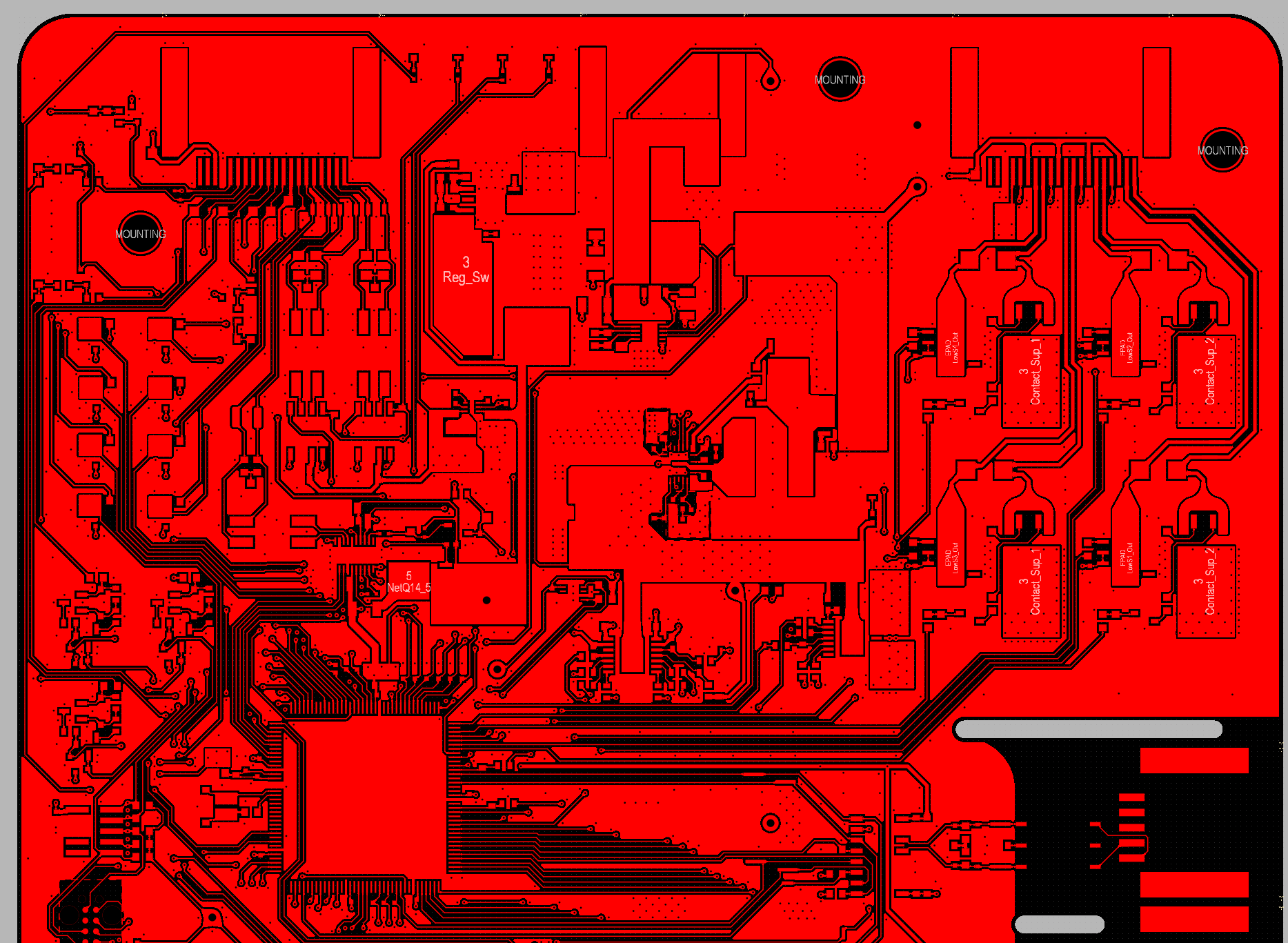
3D_Front Top Layer Inner 1 Inner 2 Bottom_Layer

EDIT:

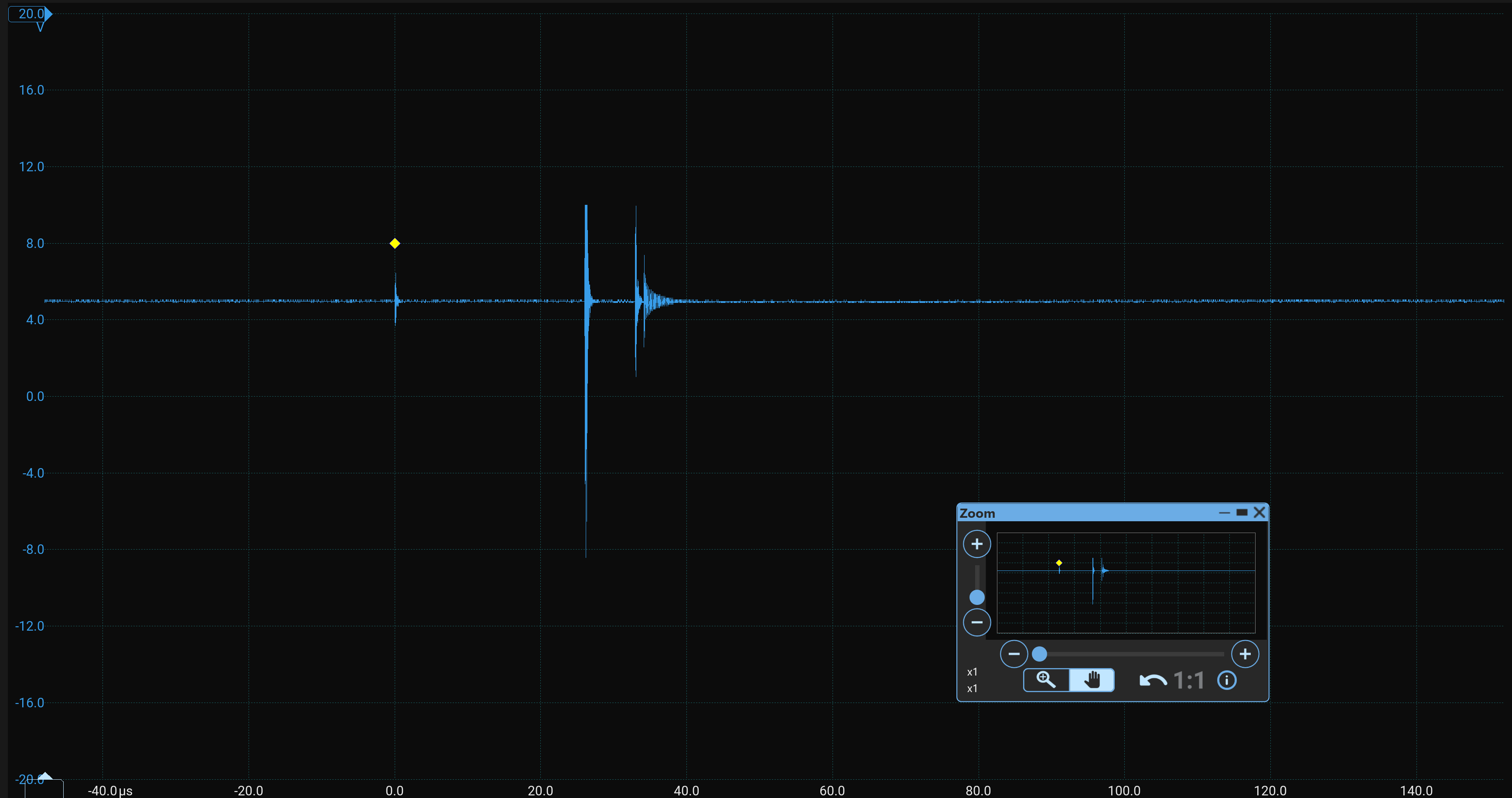
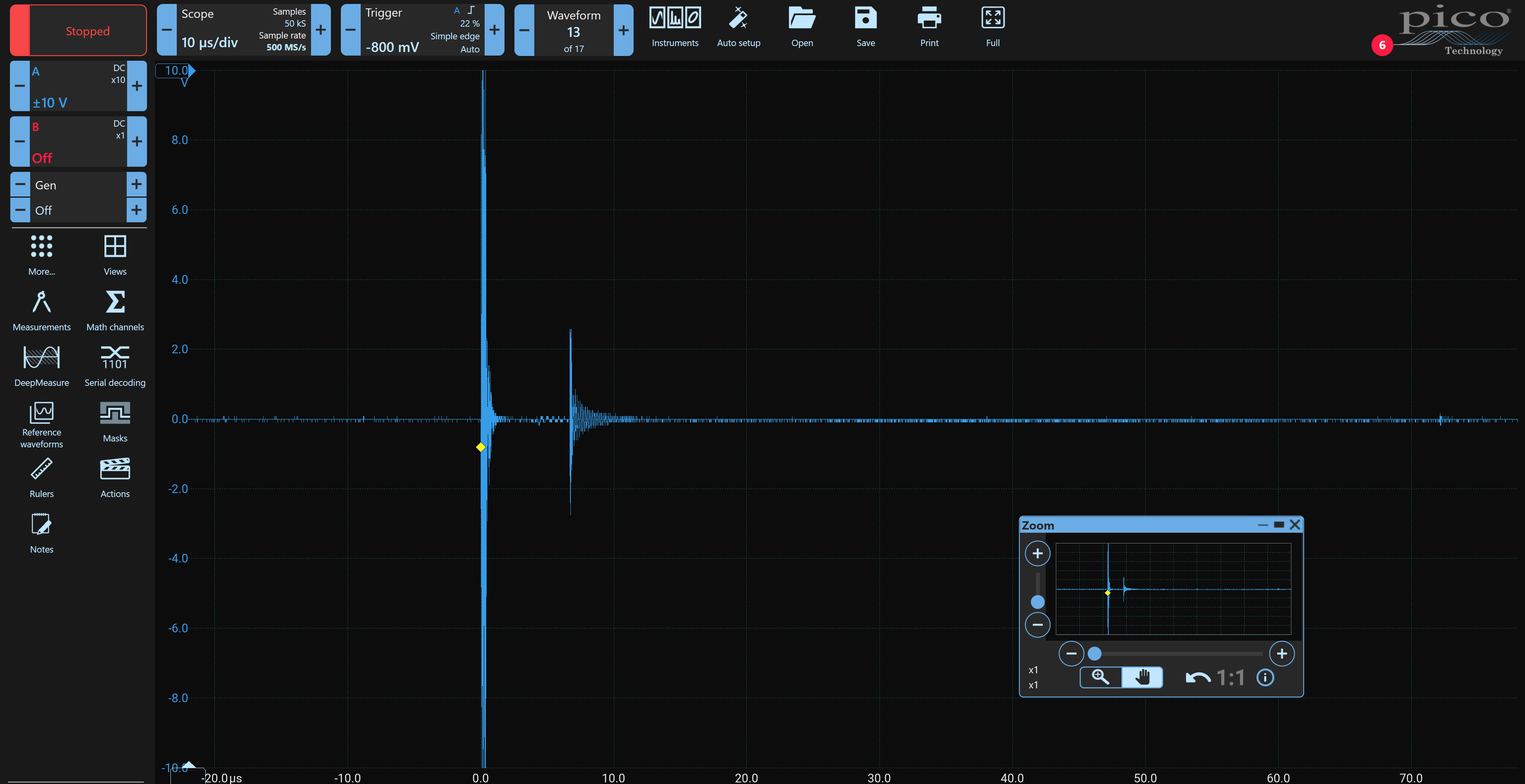
I managed to squeeze a probe in today to measure a few points. These are all captured when the contactor cuts out the MCU, luckily (Or unluckily) it was fairly repeatable.

This is the 5V supply to the MCU with my probe reference on chassis GND: enter image description here
The GND of the PCB with the scope reference on chassis GND: enter image description here
Here it is at a lower division to show more: enter image description here
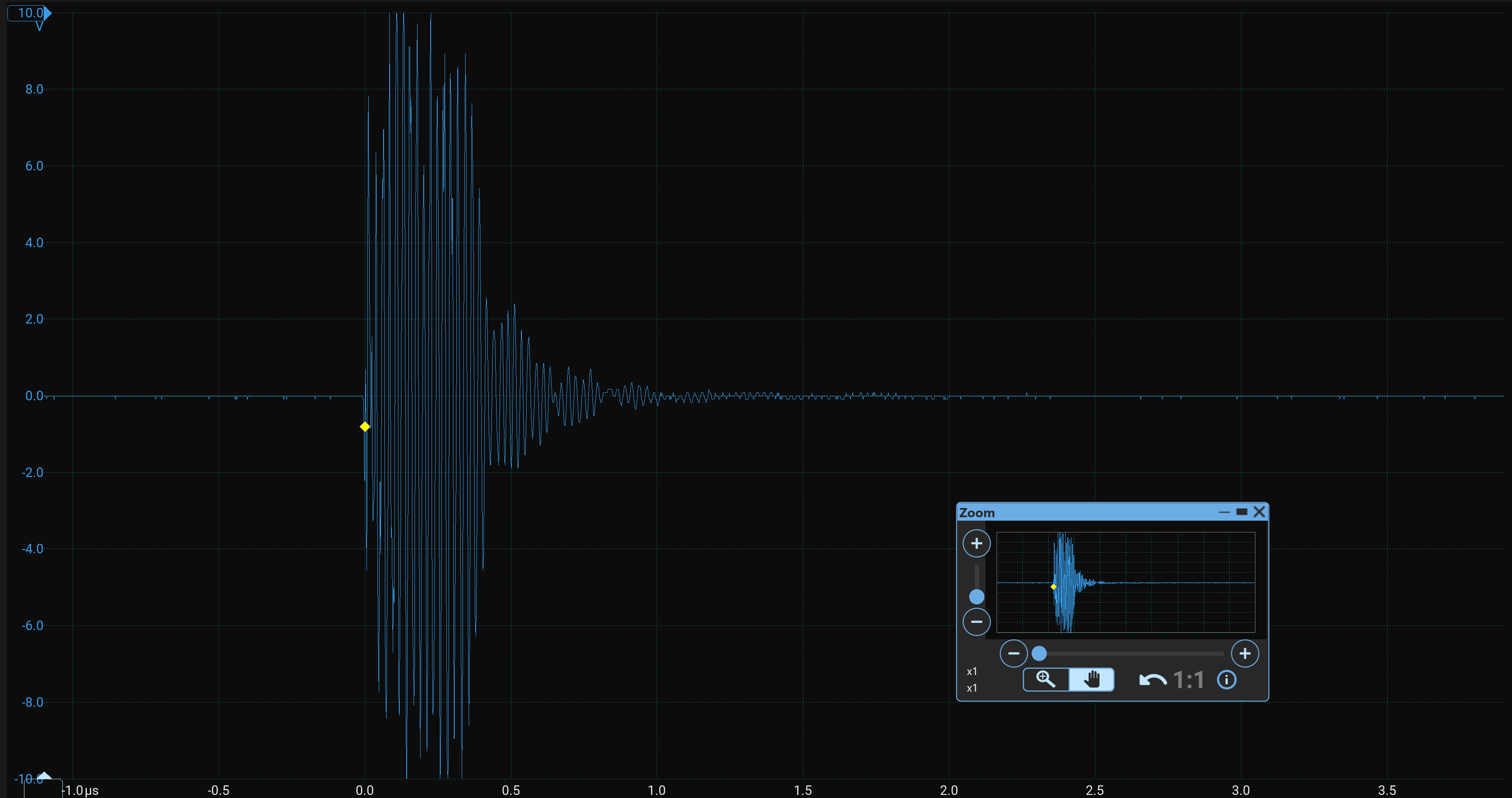
So it looks like the closing of the contactor does great some sort of interference that is seen by everything in the circuit. I am just not sure how to fix this in the board revision.

For this unit I don't have tiem for new boards so I was thinking of using ferrites around the contactor cable to see if any of there spikes are filtered out.

\$\endgroup\$
18
  • \$\begingroup\$ Were the contactors disconnected from their loads? Are the high-side switches appropriately chosen? \$\endgroup\$
    – Andy aka
    Commented Nov 11 at 10:11
  • \$\begingroup\$ Hi @Andyaka, the contactors are in a sealed box so no disconnection should be possible. Difenenitely not between the reset and then the successful second attempt. HS switches are rated for 60V 5.5A continous with much higher current peaks so probablyu the other way and overspecced to be honest! \$\endgroup\$
    – Matt
    Commented Nov 11 at 10:16
  • \$\begingroup\$ No, did you disconnect the loads from the contactors to try that out? If not you should. \$\endgroup\$
    – Andy aka
    Commented Nov 11 at 10:18
  • \$\begingroup\$ You need to figure out if this happens due to power supply brownout/ground lift, or EMI interference. The possible mitigations vary. Get one on your desk, and turn it off/on a hundred times without any loads on the contactor. \$\endgroup\$
    – Jeroen3
    Commented Nov 11 at 10:23
  • 1
    \$\begingroup\$ If you can disconnect the loads from the contactor and it works you have isolated the problem as being likely EMI from load switching. This technique is sometimes referred to as divide and conquer i.e. split the problem in half and see which half is the most troublesome. Fix the troublesome half. \$\endgroup\$
    – Andy aka
    Commented Nov 11 at 10:40

2 Answers 2

1
\$\begingroup\$

Thank you for sharing board design screenshots. Those are very helpful.
However, I'm not that impressed by the segmented board design, this puts components in sub-optimal placements, such as TVS diodes for contactor 3 and 1 are nowhere near the connector and basically useless.
There are also a few very long traces on the bottom. But on a four layer board this may be acceptable.

From what I can tell, there also isn't a lot a "big" capacitance to go around. Most ECU's (looks like one) need to support several milliseconds power glitching. And you've already determined that you need 300ms delay between relay activations.

Unfortunately you will need to get an unsealed board and start probing.
Even if we could tell what the problem is through our crystall ball, you can't fix it while potted.
(don't ask how I know)

  • Simplify the firmware, make sure it isn't a firmware bug.
  • Check what the mcu reports as reset source.
  • Check to see if you have brownout, the lack of electrolytics makes me suspicous.
  • Measure power supply ripple during relay activiations.
  • Check other switching regulators do not crash.
  • Validate your clocking does not fail. Try running the chip on internal clocks and test again.

And if you get really desperate:

  • Investigate if the fields of the relays do not cause disturbance. You can do this by switching a contactor with another relay and psu and have the wires go over/under the unit.
  • Another cheap check is the piezo-electric lighter test. ('click' it nearby)

This is all assuming electrical, can the shock of relay activation cause it? Hammer the table with the unit on it?

You can also take your board to a emi consultant and have their instruments try to replicate the issue. Some are very helpful and have seen many issues.


We've had an issue like this, a customer kept returning board that would boot-up in self-test failure. It's odd, we could never replicate this problem with those boards.
We've spent weeks trying to turn it on and off seeing if you could get it into this failure state. Changed firmware, added delays, made selftests slower/faster... Eventually we visited the client, he had more than a hundred meter of cable from the 24V source to the panel with our board and a plc. This caused powerup to be very non-linear in the first few moments.
We've added a 24V isolator to the panel and the problem has been resolved ever since.

\$\endgroup\$
7
  • \$\begingroup\$ Hey, thanks for the in depth response! Split my response as I would hit the max character count if not! Firstly I agree with the segmented comment. I dropped the ball on the contactor drive section by mistakenly going for layout aesthetics instead, I am currently modifying the board for future releases and this is one of the improvements. As for the long bottom trace, I assumed this is always better than going up and down through layers as both middle layers are GND. Why would this be bad routing on bottom layer? \$\endgroup\$
    – Matt
    Commented Nov 12 at 0:04
  • \$\begingroup\$ I was planning on adding an extra 220uF eCap after the input protection circuit and before the range of buck/buck-boost converters. What level would you normally expect to see? I tried to calculate based on ripple from DCDC converters datasheet but I could be missing something obvious The boards are not potted luckily, just have tricky access without breaking the unit's wet seal. I am going to go through and check the list you have mentioned, thank you! \$\endgroup\$
    – Matt
    Commented Nov 12 at 0:04
  • \$\begingroup\$ I am currently updating the board so I am really desperate to find this issue. I am still not convinced it is not due to a ground loop or current return when that initial 4.3A current is pulled due to the pickup current of the contactor, I just don't know how to get around this! \$\endgroup\$
    – Matt
    Commented Nov 12 at 0:05
  • \$\begingroup\$ Hey @Jeroen3 I have added some scope images of what I was able to get a probe to today. The MCU reports a reset due to "External Reset Pin" so I assume this spike is creating a very quick drop out in the reset line and the MCU supply is ok due to capacitiance? Thanks! \$\endgroup\$
    – Matt
    Commented Nov 12 at 22:01
  • \$\begingroup\$ @Matt please use the little metal spring when measuring this, do not use chassis ground. \$\endgroup\$
    – Jeroen3
    Commented Nov 13 at 7:21
0
\$\begingroup\$

You are powering the unit with 12Volts. Does the DVM show a voltage drop when the contactor closes? If so Add a capacitor to the input power 2200mfd/ 35 volts is good to test with. If this solves the problem, that indicates you have a power suply that has bad caps and is failing.

\$\endgroup\$

Your Answer

By clicking “Post Your Answer”, you agree to our terms of service and acknowledge you have read our privacy policy.

Not the answer you're looking for? Browse other questions tagged or ask your own question.