6
\$\begingroup\$

In the following article on overclocking a Pentium from 1GHz to 5GHz using liquid nitrogen: The 5GHz Project, there is an assertion that "Heat dissipation rises exponentially during extreme overclocking". However, in this post on CPU power heat: How are the CPU power and temperature caculated/estimated?, it appears that work is linearly proportional to frequency, as follows:

To work out the work done whenever the gate changes state you can model it as a capacitor with some effective capacitance, \$C_g\$, and you get:

$$W = \frac{1}{2}C_gV^2$$

and the power is the work per state change times the number of state changes per second, so:

$$P_g \propto C_gV^2f$$

If you add up all the logic gates in the processor you can define an effective total capacitance, \$C\$, that will be the sum of all the gate capacitances, \$C_g\$, so:

$$P \propto CV^2f$$

The 5GHz project page then states "In the past we recorded about 135 watts using the Chip-con compressor at 4.1 GHz. Using our nitrogen cooling to break the 5 GHz sound barrier would produce peak heat dissipation of up to 180 watts emitted from a die surface area of 1.12 square centimeters. Applied to our example that means 1.6 MW per square meter."

I asked the above question in the context of the question How are the CPU power and temperature caculated/estimated?. My follow-on question was deleted but I got this reply before it was deleted:

The formula only suggests a linear increase with respect to frequency if the voltage is held constant, which is not going to be true for large overclocks such as this one. The CPU becomes unstable at high frequencies, which can be partially compensated for by increasing the voltage. Thus, for large overclocks, the power grows faster than linearly because of this accompanying voltage contribution. I don't think it's literally exponential, however; that may be just imprecise language. The details would probably be better left to another SE site.

Probably the 5GHz people meant to say "increases quadratically", assuming that as they increase frequency, voltage is also increased proportionally to level necessary for chip to function reliably. What is the equation relating frequency and required voltage level for a chip which operates stably at frequency F and voltage V? Note that for GPU such as AMD HD7850, I can set the clock frequency without changing the voltage supplied to the chip, so it is not automatically the case that changing the frequency implies a change in supplied chip voltage. Clearly at some point my chip will stop functioning properly, so it would be helpful to have an equation showing how much to increase voltage as a function of frequency. Also note that some GPU users undervolt the chip, why would they do this?

Under the assumption of quadratic heat rise in frequency/voltage, it would be more efficient to have 5 processors running 1GHz rather than 1 processor running at 5GHz, is this correct? I.e. space is quadratically cheaper than time, is that more or less correct? How to correctly state this tradeoff?

In this response to a question on How Modern Overclocking Works, @Turbo J says

You can increase the clock frequency further when the voltage is higher - but at the price of massive additional generated heat. And the silicon will "wear out" faster, as bad things like Electromigration will increase too.

So again, the question is what is the equation that models "massive additional heat", is "massive" quadratic, i.e. are we still talking about the work equation above?

\$\endgroup\$
16
  • \$\begingroup\$ As you posted, it is a linear relationship to clock frequency in a simplified model. It has a stronger dependence on the voltage. People overuse 'exponentially'. \$\endgroup\$
    – HL-SDK
    Commented Sep 5, 2013 at 18:29
  • \$\begingroup\$ "That is, if I am driving an oscillating signal twice as fast, if the voltage is the same, I expect each peak voltage to be half as much, is that right?" No it is not right. \$\endgroup\$
    – cksa361
    Commented Sep 5, 2013 at 21:33
  • \$\begingroup\$ OK cksa361, please help me understand how much I need to raise voltage on an overclocked GPGPU in order to maintain signal levels. According to another poster, I needed to raise levels as a function of frequency increase. \$\endgroup\$
    – user29254
    Commented Sep 5, 2013 at 21:39
  • \$\begingroup\$ Regarding your comment: Back in the days we performed overclocking by trial and error. 1.Increase frequency until component becomes unstable. 2.Increase voltage a tiny bit and check if stability improved. If yes, repeat step 1, if no repeat step 2. Stop as soon as temperature becomes a problem or system is too unstable. \$\endgroup\$
    – Rev
    Commented Sep 5, 2013 at 22:03
  • 1
    \$\begingroup\$ Don't get too hung up on their use of the word 'exponential'. That article is full of hyperbole. \$\endgroup\$
    – mng
    Commented Sep 6, 2013 at 4:05

1 Answer 1

6
\$\begingroup\$

In general:

Take whatever physical system to an extreme, and all the simple models which were developed by engineers will break apart.

Simple model for active power dissipation:

The statement about an exponential increase in heat dissipation at extreme overclocking is not consistent with the following equation:

$$P_g \propto C_gV^2f$$

but how the above equation was derived?

Well, it is based on the following simplification:

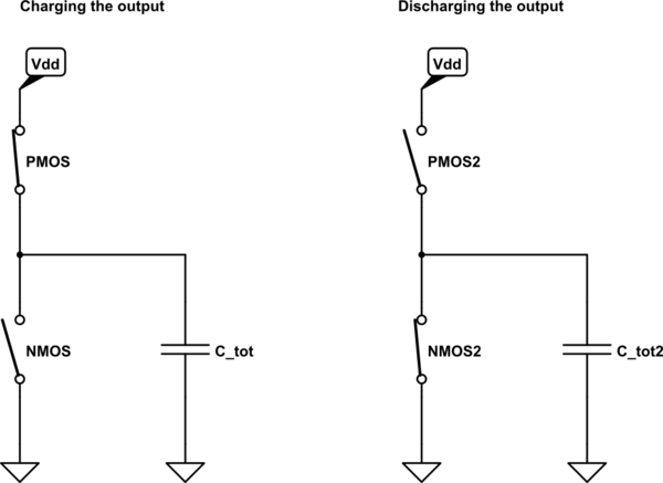
schematic

simulate this circuit – Schematic created using CircuitLab

This model assumes that:

  • Transistors behave like an ideal, mutually exclusive switches (no overlap in time when both switches are ON)
  • All capacitances may be represented as a single equivalent capacitor at the output
  • No leakage currents
  • No inductances
  • More assumptions

Under the above assumptions, you can think of inverter's (or any other logic gate's) action as of charging the output capacitor to \$V_{dd}\$ (which consumes \$\frac{1}{2}C_{tot}V_{dd}^2\$ Watt from the power supply), and then discharging it to ground (which does not consume additional power). The frequency factor \$f\$ is added to represent an amount of such cycles per second.

In fact, it is surprising that the above equation may be an accurate estimation of dynamic power at all, given the huge amount of non-trivial assumptions made. And indeed, this result may be used for the first order analysis only - any serious discussion of power dissipation in modern CPUs can't rely on such a simplified model.

How the simple model breaks:

All the assumptions made while developing the above simplified model break at some point. However, the most delicate assumption which can't hold for an extreme frequencies is that of two mutually exclusive ideal switches.

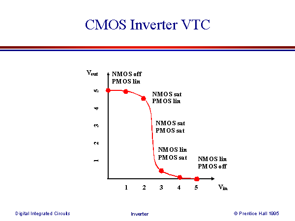
The real inverter has non-ideal Voltage Transfer Curve (VTC) - a relation between inverter's input and output voltages:

enter image description here

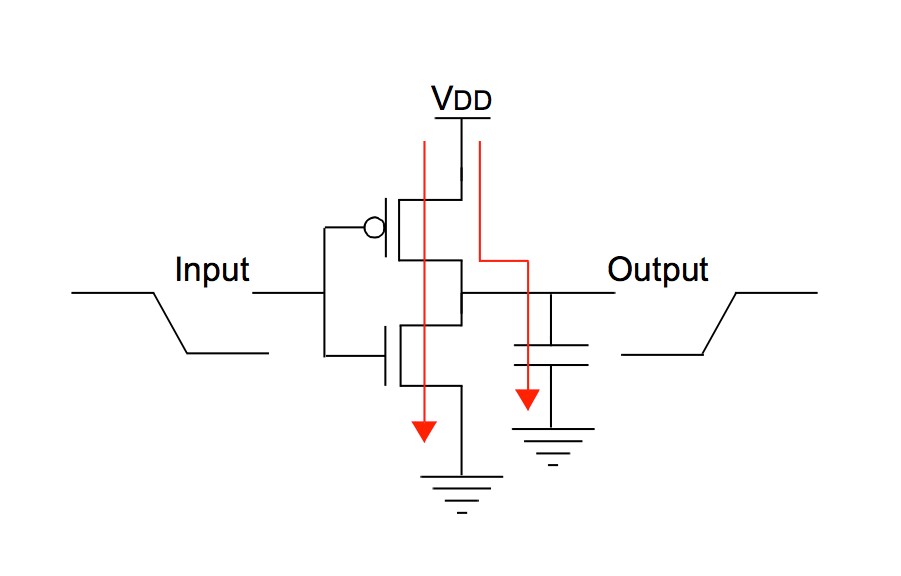
On the above VTC the operational modes of both NMOS and PMOS were marked. We can see that during switching there will be time when both NMOS and PMOS are conducting at the same time. This means that not all the current drawn from the power supply will flow to "output capacitor" - part of the current will flow directly to ground, thus increasing the power consumption:

enter image description here

What this has to do with frequency:

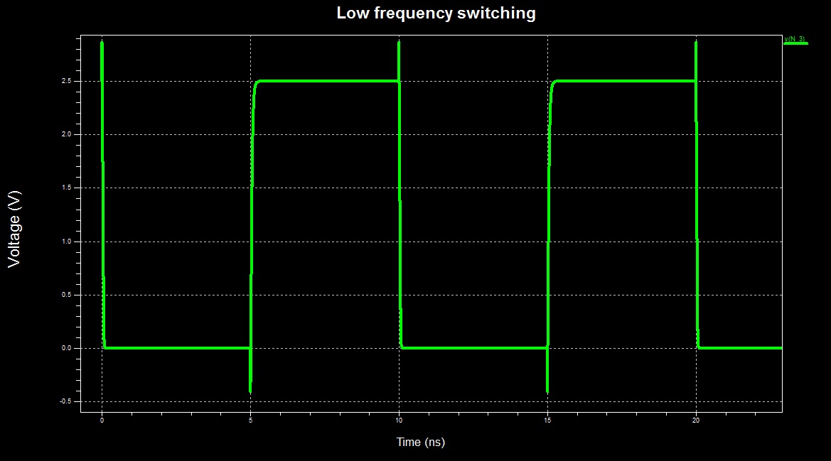
When the frequency is relatively low, the switching time of the inverter comprises negligible part of the total operational time:

enter image description here

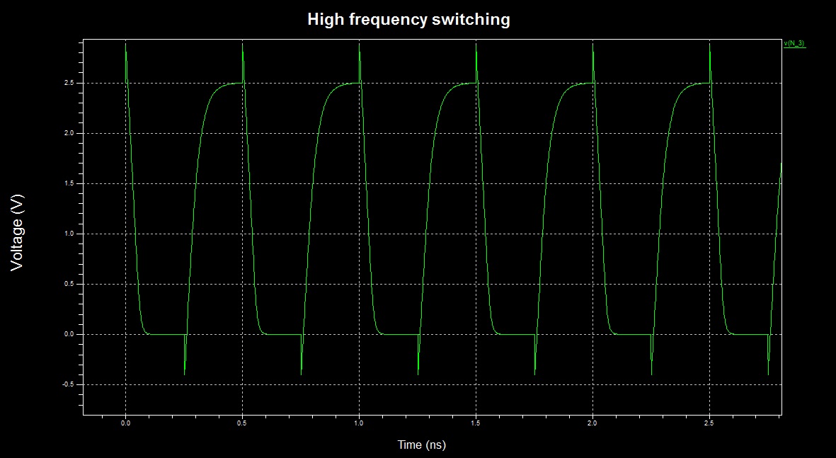
However, when the frequency is pushed to the limit, the inverter "switches continuously" - it is almost always in switching activity, thus dissipating a lot of power due to direct ground path for the current (time scale changed):

enter image description here

Maybe it is possible to try to model this and see if the result is exponential, but I prefer to use simulations (however, the simulation will account for all non-idealities, not just this one).

Simulation results:

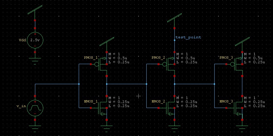
In simulation I measured the total energy (integral of power) drawn from an ideal power supply by an inverter in the following configuration:

enter image description here

The first and the last inverters are there just in order to model a real driving and loading conditions.

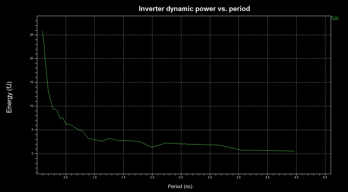
The dissipated energy as a function of frequency:

enter image description here

We can see an approximately linear dependence for periods longer than 1ns, and clearly exponential dependence for shorter periods.

Notes:

  1. For the simulation I used an antique 0.25um transistor models. The current state of the art transistors are more than x10 shorter - I guess the divergence from the linear model is stronger is newer technologies.
  2. The question whether a particular CPU/GPU can be overclocked such that it enters the exponential frequency dependence state while still stable and functional is device specific. In fact, it is exactly what overclockers try to derive empirically - to what frequency can a given device be pushed without malfunctioning.
  3. All the above results and discussions do not consider changing voltage levels. I guess there is no way to analytically predict the outcome of simultaneous change of both frequency and voltage - the only way to find out is to perform an experiment.

From a single inverter to CPU:

CPUs mainly consist of logic gates, which are conceptually similar to an inverter. However each modern CPU has sophisticated measures of controlling its operating frequency, operating voltage and can turn off its submodules during runtime. This means that the heat dissipation trend of the whole processor may be slightly different than this of the single inverter. I guess that the statement about exponential increase in heat dissipation during extreme overclocking is a bit of exaggeration, but we are not mathematicians: either it is exponential, or \$\propto f^{3+}\$ - it is all kind of "bad".

\$\endgroup\$
9
  • \$\begingroup\$ Hi @Vasiliy Zukanov, can you quantify the tradeoff between 5 CPUs running at 1GHz vs 1GPU running at 5GHZ, in Watts/cycle? Do 5 air cooled slow processors make more economic sense than 1 liquid nitrogen cooled fast processor? This is non-obvious in the sense that there is a market for liquid cooled machines (all Crays in their day) and liquid cooled cards, e.g. a new liquid-cooled double Radeon HD 7950 just came out: ARES2-6GD5. Liquid cooling is used to push towards the dicey end of the curve \$\endgroup\$
    – user29254
    Commented Sep 7, 2013 at 14:48
  • \$\begingroup\$ Also here is a lab report on ARES2-6GD5. \$\endgroup\$
    – user29254
    Commented Sep 7, 2013 at 15:07
  • \$\begingroup\$ @user29254, too many factors involved: the architecture of CPUs and GPU, their microarchitecture, the fabrication technologies of both, SW architecture, the overhead of operating system, many more... I don't think anyone can give you an accurate comparison - even if you'll get both manufacturers sitting in the same room. The only thing is that GPUs usually have HW modules for special calculations (which may take many cycles in CPU) - try to see whether the algorithm you want to run will benefit from GPUs HW. If not, I'd say go for 5 CPUs. \$\endgroup\$
    – Vasiliy
    Commented Sep 7, 2013 at 15:27
  • \$\begingroup\$ Hi @Vasiliy Zukanov, the question is really about rack configurations and water cooling for GPGPU mining and password cracking. For example this rack uses air cooling and MOSIX OS from Israel and the rack designer says that water cooling is a waste of time: AMD Cluster \$\endgroup\$
    – user29254
    Commented Sep 7, 2013 at 16:47
  • \$\begingroup\$ Also, the lab report on ARES2 says at peak load card reaches 625W which exceeds supplied 575W. My conclusion from all this is that bundling 2 GPUs into one watercooled card is a waste of time vs just plugging 2 cards into a properly powered motherboard. \$\endgroup\$
    – user29254
    Commented Sep 7, 2013 at 16:54

Your Answer

By clicking “Post Your Answer”, you agree to our terms of service and acknowledge you have read our privacy policy.

Not the answer you're looking for? Browse other questions tagged or ask your own question.