3
\$\begingroup\$

I want to use a small 5x7 LED Matrix on a ATmega.

I havn't that much space, so I don't want to use a dedicated driver chip.

My thought would be to switch the columns via a transistor and use a resistor on the rows to limit the current.

After a little bit research I found some products wchich use the a LED Matrix without a current limiting resistor and even transistors:

https://wiki.raumzeitlabor.de/wiki/Hacklace/en http://www.adafruit.com/products/950

How does this work? In my understanding, the current of all colums (or rows, depending on the multiplexing) adds up on the row (column) pin and exceeds the current limit of the µC pin. And also the lack of current limiting resistors seems a little bit strange.

The only way I could think of this would reliably work is that the current is limited via the multiplexing timings. Is this the case? And is there a way to calculate such things?

\$\endgroup\$
5
  • 2
    \$\begingroup\$ I believe it's known as going off-datasheet, pushing your luck (hopefully in an informed manner). If you're charlieplexing a load of relatively low-power LED's then each pin is only working a bit outside its limit for a brief period and hopefully that means it won't burn out. Notice that neither of those links are for safety-critical or high-value applications, if your LED necklace stops working you go "meh" and chuck it in the trash. \$\endgroup\$
    – John U
    Commented Sep 19, 2013 at 9:18
  • \$\begingroup\$ Yes, that's what I also assumed. But I thought that maybe there is a way to "calculate" the risk. \$\endgroup\$
    – Johni
    Commented Sep 19, 2013 at 9:26
  • 1
    \$\begingroup\$ The clue in those links is the words "coin cell included" - there's your current limiting and it's quite effective. \$\endgroup\$
    – user16324
    Commented Sep 19, 2013 at 9:27
  • \$\begingroup\$ @Johni - there absolutely IS a way to calculate the risk, if you dive into the chip design you can usually find the topology of the IO circuitry and work it out from there. \$\endgroup\$
    – John U
    Commented Sep 19, 2013 at 9:43
  • \$\begingroup\$ Ok, I also will use a coin cell but I think I will use resistors and transistors (or an ULN2003). But I think I only need the transistors for ether the rows or the cols since one single led can be handled by a pin on the µC. Or do i miss something? \$\endgroup\$
    – Johni
    Commented Sep 19, 2013 at 10:15

2 Answers 2

3
\$\begingroup\$

At least three factors contribute to the use of an LED matrix without current limiting and without drive transistors:

  1. High internal resistance of power source: Small batteries such as CR2032 are routinely used for throw-away LED toys, mini flashlights, throwies and the like, with no resistor attached. Because of the battery being incapable of delivering high currents over a sustained period, at worst there is a brief instant during which current over the LED's rating, or that of the microcontroller's GPIO, might flow. Thus, neither a limiting resistor nor a drive transistor is used. A good article around this is "Some thoughts on throwies". However, see also third point.
  2. Multiplexing: By switching LEDs in a multiplexed pattern, the effective current through any given LED, and through the GPIO pin, is kept low. This is however determined by both the effective duty cycle seen by each LED, and by the multiplexing frequency.
    • For example: 8 rows of LEDs multiplexed on one pin would make the effective duty cycle per row ~12.5%. Thus effective current seen by each row of LEDs would be around that much of the maximum... Not exactly, though, as switching time reduces the actual on-time per cycle. Raise the frequency of muxing high enough, and the effective current drops significantly - but make it too high and at one point the LEDs just won't light up visibly.
    • The other impact of multiplexing frequency is that too slow is unhealthy: Even at a 5% duty cycle (say 20 LEDs) for instance, if the time for each cycle is too long, LEDs will be destroyed before one cycle's on-time is over, so duty cycle becomes irrelevant. Manufacturers of cheap LED toys can easily determine a workable frequency by destructive testing, since individual nameless LED batches might have different duration of tolerance for over-current.
  3. LED forward voltage: The driving energy for the current to flow through the LED is related to the voltage difference between (a) what the battery supplies, and (b) the total of LED forward voltage, voltage drop across any switching BJTs or MOSFETs, and anything else in the series path. Of these, the LED Vf is a big chunk: Some LED colors, such as infrared, red, and certain types of yellow, green and amber, represent a low forward voltage, between 1 and 2 volts, roughly. On the other hand, colors such as blue, white, UV, some types of yellow and green, represent a higher forward voltage, for example 2.5 Volts and up. Thus, in the high voltage colors, the available headroom to the CR2032 cell's nominal 3 Volt supply is smaller, and hence the current available after overcoming battery internal resistance is lower.
    • In short, the high Vf LED colors are typically safer to use with a 3 Volt coin cell. For LEDs rated below 1.5 Volts, similarly, a 1.5 Volt coin cell e.g. LR44, can be used.
    • LEDs requiring more than the actual voltage the battery can supply under load, will simply not light up. This includes some types of white LED which require voltages close to or greater than the CR2032 battery nominal.

Summary: Keeping the above in mind, try it and see if it works for you. At worst, you would lose a microcontroller or two, or a few LEDs, but you will know how much cost you can cut in production.

\$\endgroup\$
1
  • \$\begingroup\$ Thanks for the background informations. I already tried it with current limiting resistors for every column and the LEDs are very dim. I will try it without them, later. \$\endgroup\$
    – Johni
    Commented Sep 19, 2013 at 12:35
2
\$\begingroup\$

A battery, Attiny 2313 and LED matrix(this one uses 8x8). I assume you already have a programmer. http://tinkerlog.com/howto/64pixels/

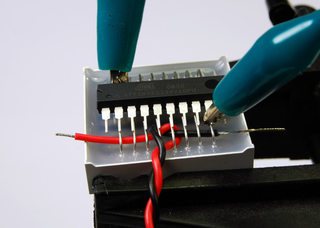
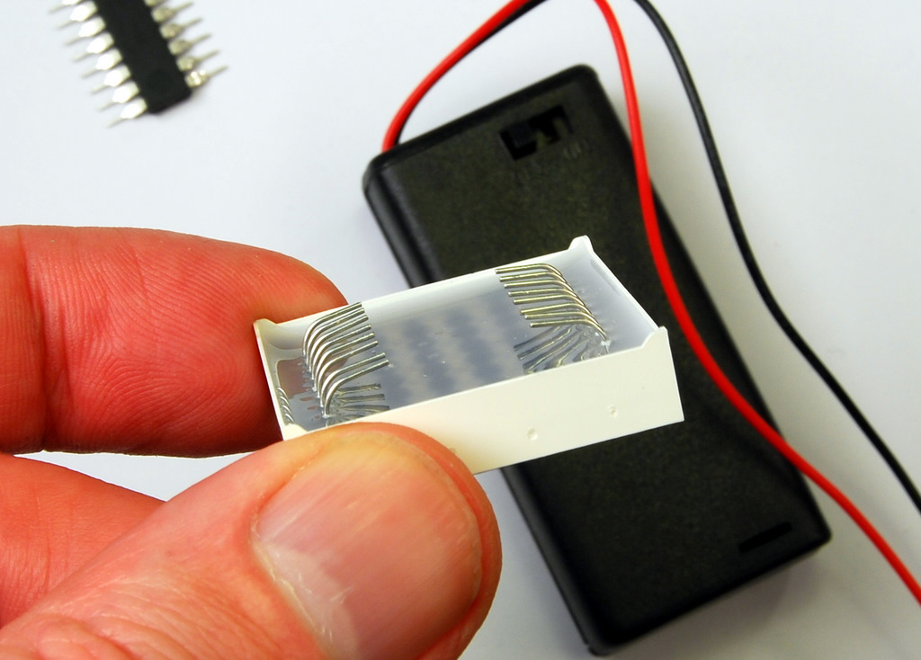
This work is done by Alex Weber. He has used an 8x8 LED matrix and an ATtiny 2313, He uses a very neat trick of soldering the the controller directly on the back of the 8x8 matrix, saving a lot of space and requires no extra components.

Bend the pins on the matrix display(8x8 shown here) enter image description here
And solder the uC directly on to it. enter image description here

if you are using mega 8/168/328p you, have to use the internal 8MHz crystal by changing the fuses, here is a nice calulator http://www.engbedded.com/fusecalc or use the following reference

Fuse atmega8 high byte HFUSE:  
0xc9 = 1 1 0 0   1 0 0 1 <-- BOOTRST (boot reset vector at 0x0000)  
       ^ ^ ^ ^   ^ ^ ^------ BOOTSZ0  
       | | | |   | +-------- BOOTSZ1  
       | | | |   + --------- EESAVE (don't preserve EEPROM over chip erase)  
       | | | +-------------- CKOPT (full output swing)  
       | | +---------------- SPIEN (allow serial programming)  
       | +------------------ WDTON (WDT not always on)  
       +-------------------- RSTDISBL (reset pin is enabled)  
Fuse atmega8 low byte LFUSE:  
0x9f = 1 0 0 1   1 1 1 1  
       ^ ^ \ /   \--+--/  
       | |  |       +------- CKSEL 3..0 (external >8M crystal)  
       | |  +--------------- SUT 1..0 (crystal osc, BOD enabled)  
       | +------------------ BODEN (BrownOut Detector enabled)
       +-------------------- BODLEVEL (2.7V)

BE CAREFUL, only program the fuses when you are absolutely sure of what they will do. Read datasheet of the micro you are using,in some micros 1 is disable(unprogrammed) and 0 is enable(programmed).

Common row anode 5x7 dot matrix LED display.
     +---+--+---+
Col1 |1  +--+ 12| Row1
Row3 |2       11| Row2
Col2 |3  5x7  10| Col3
Row5 |4  LED   9| Row4
Row6 |5        8| Col5
Row7 |6        7| Col4
     +----------+

Common row cathode 5x7 dot matrix LED display.
     +---+--+---+
Row1 |1  +--+ 12| Col5
Row2 |2       11| Row3
Col2 |3  5x7  10| Row4
Col1 |4  LED   9| Col4
Row6 |5        8| Row5
Row7 |6        7| Col3
     +----------+

So to use the above hack you need a micro controller that has 6 or 5 io pins on both side along the length of the DIP. On mega 8 Pin 20 will cause conflict, so you need to use a small wire to connect next io pin that is pin 23. Before you solder it test it on a bread board and test it again, because it will be difficult to wire the ISP lines after you have soldered it to the matrix.
Use 3v power supply, I used 2AA, the lasted about 168 hours.
The source code is in C, it has examples of animations and text scrolling.
http://pastebin.com/ysx5tvqs c file

http://pastebin.com/6MYdrg12 h file

\$\endgroup\$
8
  • 1
    \$\begingroup\$ This answer is in effect a link-only answer: It's merit is dependent on the linked content being available. When the linked page eventually dies due to link rot, this answer will have no remaining value. Please consider incorporating a summary of what you propose is the answer, within the body of your post. \$\endgroup\$ Commented Sep 19, 2013 at 10:33
  • \$\begingroup\$ Alright, I used the link because I do not want to take credit for the work that was done.I'll take care next time, thank you. \$\endgroup\$ Commented Sep 19, 2013 at 10:38
  • \$\begingroup\$ Please edit your answer to improve it as Anindo points out. \$\endgroup\$
    – user17592
    Commented Sep 19, 2013 at 10:47
  • \$\begingroup\$ In proccess.. :) \$\endgroup\$ Commented Sep 19, 2013 at 10:52
  • \$\begingroup\$ I already know this project and it is one of the reasons I asked this Question, because connecting a LED directly to a µC mostly isn's a geood idea. \$\endgroup\$
    – Johni
    Commented Sep 19, 2013 at 12:38

Not the answer you're looking for? Browse other questions tagged or ask your own question.