3
\$\begingroup\$

I'm trying to build a circuit that contains multiple 3-wire RTD PT100 sensors (12 of them). I have a microcontroller with plenty of ADC pins so I could potentially measure the RTD and the wire resistance on the ADC without an extra opamp to cancel the wire resistance out.

The question I have is about the power source for exciting the RTDs. Can I have a single current source and power all the RTDs in parallel (or should it be series?) from that single source, or do I need each of my RTDs to have a separate current source?

\$\endgroup\$

2 Answers 2

2
\$\begingroup\$

You shouldn't hook up multiple RTDs to a single current source in parallel. You would end up with more unknowns than equations. You measure the voltage across some particular RTD, but you don't know the excitation current into that particular RTD, and of course you don't know the resistance.

\$ \left\{ \begin{array}{l l} V_{RTD,1}=I_{exc,1}R_{RTD,1}\\ V_{RTD,2}=I_{exc,2}R_{RTD,2}\\ I_{exc} = I_{exc,2} + I_{exc,2} \end{array} \right. \$

I have left out the parasitic lead resistance.

\$I_{exc,1}\$, \$I_{exc,2}\$, \$R_{RTD,1}\$, \$R_{RTD,2}\$ are 4 unknowns. We have only 3 equations. So, this parallel connection doesn't work even for the case of 2x RTDs.

Either multiplex the current source and energize one RTD at a time. Or, provide an individual current source for each RTD.

If you hook up all of the RTDs in series, how are you going to measure and compensate for the lead in a 3-wire scheme? It should be possible, but I'm not sure that that would be simpler.

I would also be careful with your 2-channel A/D approach where a separate A/D conversion is made to cancel out the lead resistance in a 3-lead configuration. With an analog approach, you compensate for the lead instantly in analog . With 2-challel, you make a measurement of the RTD at a time τ1, and then you make another measurement of the lead at a time τ2. There will be 50 or 60 Hz noise from the mains. Due to noise, the state at τ2 may be different from τ1, and your compensation may introduce some error. You can alleviate this by filtering and/or canceling out the 50 or 60 Hz noise.

Analog Devices note CN-0287 describes a front end for measuring multiple RTDs. It uses a single current source. See p.4

\$\endgroup\$
1
  • \$\begingroup\$ I was originally looking at AN687 with a circuit for doing a single RTD using a quad opamp, and was hoping to be able to condense my number of opamps significantly with a single current source. Your answer explains very well why I can't do that. I've basically just copy/pasted AN687 for each of my RTDs. \$\endgroup\$ Commented Dec 5, 2013 at 16:16
0
\$\begingroup\$

This answer is about using a precision resistor to feed the RTD from a precision voltage source. Clearly, if wanting to measure multiple RTDs, a single resistor per RTD circuit is simpler than a current source and, as per your question no, you can't wire the RTDs in series.

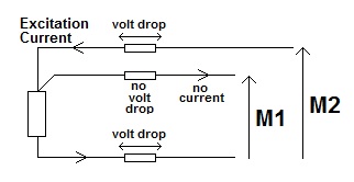
With a 3-wire RTD connection you need to measure two voltages: -

enter image description here

The difference between M1 and M2 is the volt drop down the top feed wire and it can be presumed that the same volt drop is down the ground return wire therefore actual voltage across RTD is M1 - M2. To convert this to temperature you need to know the current down the wire and this can be achieved by using a precision current source (i.e. it has a known value).

If you used a precision resistor from say 5V and you used your ADC to measure its volt drop you then know what current is flowing. You did say you have plenty of ADC inputs!

If your ADC's voltage reference can be tied to the same voltage that feeds the precision resistor, measurement M2 tells you the volt drop across the precision resistor and, if the supply voltage is stable and reasonably precisely known then this tells you what the current is. This now just requires two ADC measurements.

An earlier answer cautions about the use of non-simultaneous ADC measurements because AC mains induced on the wires will create an error voltage term. I also want to mention that the ADC input impedance may not be as good as you would like - I'm mentioning this in case you were thinking of using the ADC directly on the lines, especially the "third" (zero current) wire.

\$\endgroup\$

Your Answer

By clicking “Post Your Answer”, you agree to our terms of service and acknowledge you have read our privacy policy.

Not the answer you're looking for? Browse other questions tagged or ask your own question.