5
\$\begingroup\$

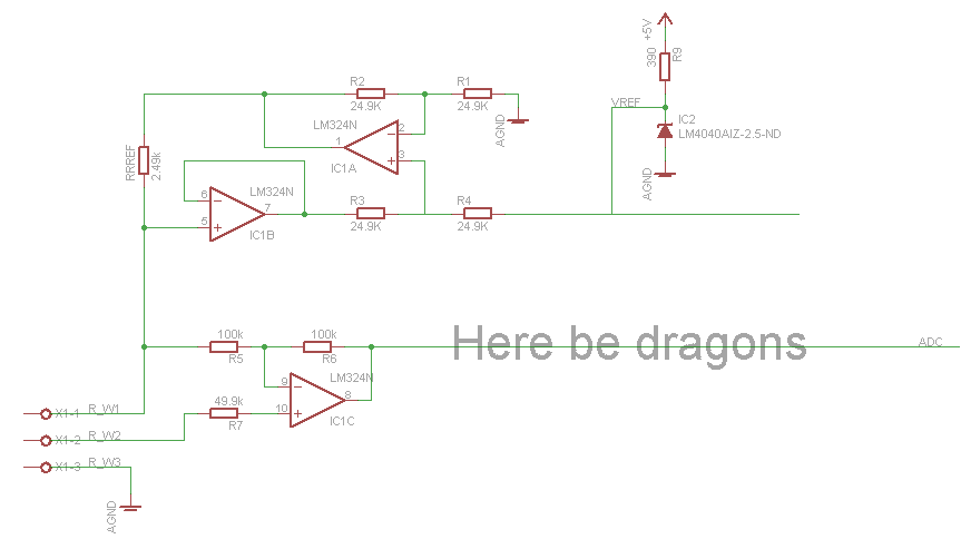
I'm trying to hook up my 3 wire PT100 RTD probe to an Arduino, but end up out of my depth when it comes to the whole op amp circuit design. I have stolen the 1mA current source and wire compensation design from Precision Temperature Sensing with RTD Circuits, but as my RTD is good for -50 to 200C, the final stage isn't directly transferable.

Looking at a PT100 resistance table, at -50C resistance at the probe is 80.31Ohm and at 200C 175.81Ohm. With the 1mA excitation current that should give a voltage from 80.3 to 175.8mV as far as I can tell. Ideally I want to amplify and bias that signal so it roughly fits the 0 to 2.5V range the ADC is measuring, but I'm not sure how to do that. Another question I have is whether I want a low pass filter like in the application note, guessing it depends on the noise, particularly from the power supply (and AVR?). Note I don't have a -5V supply available, so it'll have to be a single source amplifier.
enter image description here

\$\endgroup\$
5
  • \$\begingroup\$ That's hilarious. I basically independently derived that exact current source topology for a project I was working on recently. I guess I'm doing something right! \$\endgroup\$ Commented Oct 18, 2012 at 8:19
  • 4
    \$\begingroup\$ As an aside, dragons are very bad for electronics. They tend to lead to scorched PCBs and overheated ICs. However, if you carefully train them, I hear they're great for solder-paste reflowing. \$\endgroup\$ Commented Oct 18, 2012 at 8:19
  • \$\begingroup\$ I've built the design based on AN687 - github.com/Miceuz/reflow-oven-controller as fas as I understood it's single supply, you just have to select the opamp with a low offset voltage, like microchip's MCP609 \$\endgroup\$
    – miceuz
    Commented Apr 16, 2013 at 5:29
  • \$\begingroup\$ If you're lazy and/or have a four-wire RTD, you can always cheat and use an off-the-shelf instrumentation amplifier. \$\endgroup\$ Commented Apr 16, 2013 at 6:39
  • \$\begingroup\$ @Nick Alexeev Please update with your progress or success with above circuit. You have replaced MCP609 with LM324 OpAmp. They are surely different in specs. I was also trying to test same circuit with LM324. But got no Success and eventually thought that LM324 is not up to for the task. MCP609 will be must. Since your are talking for the same thing here, I wish to know weather you got it working? If you made any changes apart from App Note then pleas let me know. Thank You. \$\endgroup\$ Commented Jan 24, 2019 at 5:39

1 Answer 1

2
\$\begingroup\$

I think you would want to simply use the circuit topology of Figure 5 of that Microchip App Note AN687. The circuit design appears to be pretty reasonable to me. With your lower range of signal you would need to increase the gain of A4 a bit. With your quoted range 80.3 to 175.8 mV you could raise the gain up to a value of about 13. Adjusting the gain setting resistors R10 and R11 to some standard values of R10=2.00K and R11=24.0K will result in this gain of 13. At a gain of 13 the output of A4 then will be in the range of 1.043V to 2.320V. With that simple change the design of the filter would not need to change at all.

If you did want to try to add in some offset to the signal so as to be able to use more of the A/D converter range at the low end then the filter design would likely have to change which adds more work. Although LT-Spice can be your friend in helping to analyze a filter design to see if you can get it to give the responses that you would expect.

Note that the whole App Note design is based on the premise that the opamps in the circuit are biased around a center point in the supplies of 0V. This means that you would need a bi-polar supply to the amplifier packages. For the low currents reqired in this circuit you should be able to easily produce a negative supply for your use. To do this I could recommend that you deploy the bog standard MAX232 chip as a voltage doubler and inverter to produce a nomimal -7 to -9 volts off the +5 volt supply. Then use a simple -5V linear regulator and a couple of capacitors to regulate the negative voltage down to -5V. A generic 7905 type part could do the trick here.

\$\endgroup\$
1
  • \$\begingroup\$ I don't see anything in that schematic that would require a negative rail. Assuming you're using a decent, rail-rail op-amp, it should be fine on a 5V single-supply. \$\endgroup\$ Commented Apr 16, 2013 at 6:42

Your Answer

By clicking “Post Your Answer”, you agree to our terms of service and acknowledge you have read our privacy policy.

Not the answer you're looking for? Browse other questions tagged or ask your own question.