1
\$\begingroup\$

I have two digital input modules that must match: IEC 61000-4-2 ESD Contact 6kV and Air 8kV IEC 61000-4-4 EFT 1kV IEC 61000-4-5 Surge Line to line 0.5kV and Line to Earth 1kV

First module: 32 digital inputs 24VDC

Second module: 16 digital inputs 220VDC

The modules will be placed in metal rack and will pass the tests inside it.

These module don't have any embedded protection and only way to add it is to make an extension board that have TVS, MOV or smth else.

I have some ideas but I don't know do I think in right way. For 24V I use TVS diodes but 1) is nominal right? 2) SMBJ or SMCJ? 3) what is right placement of TVS (1,2,3)?
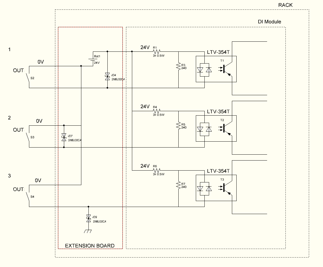
24VDC

For 220VDC module there is no such TVS, and I used MOV.

1) For ESD MOV is not the best solution, but what alternative do I have? 2) MOV has rather big Clamping Voltage, is it nominal safe for the module? 3) what is right placement of MOV (1,2,3)?

Any advices? Thanks!

ltv-354T:http://www.mouser.com/catalog/specsheets/LTV-354T%20Series-1308.pdf

220VDC

\$\endgroup\$

1 Answer 1

3
\$\begingroup\$

I've only focused on IEC 61000-4-2 ESD Contact 6kV to make the answer fairly short: -

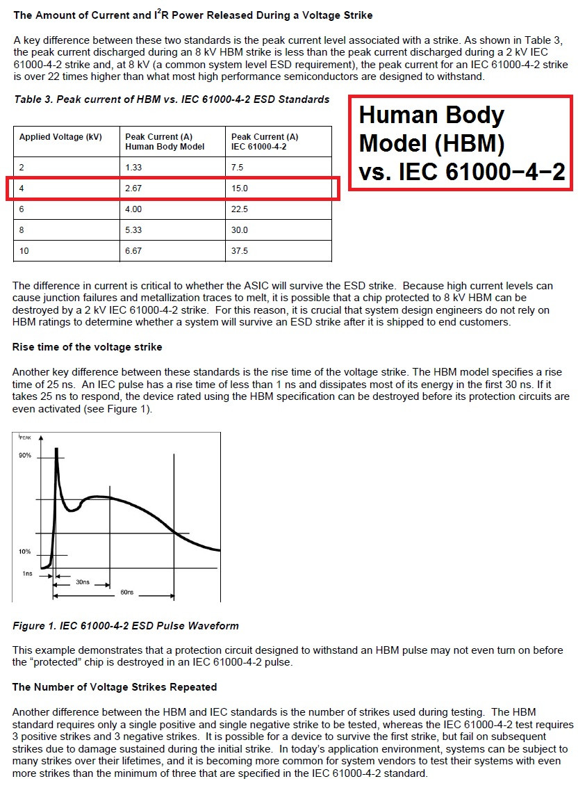
This document might start to help. It gives decent guidelines for some of the tests specified and should allow you to design things better: -

enter image description here

The 6kV test is shown below (sorry for highlighting the 4kV test by mistake). Clearly you have to withstand a peak impulse of up to 22.5 Amps and this can rise to maximum in 1ns.

You must ask yourself - "what are you trying to protect" and my guess is the opto-coupler and for the AC input version there is 56kohms in series and 240 ohms to ground. So then ask yourself if that potential divider is good enough - 50kohm to 350 is a 234:1 attenuator that means 6kV becomes a peak of about 26 volts across the 240 ohm. Given that the impulse is all done after about 100ns it makes me think that a simple capacitor across the 240 ohm will limit the voltage rise that the opto may see.

It might be worth simulating these scenarios to see what you can reasonably get away with.

Please don't forget to verify that the 56k used is capable of withstanding a 6kV pulse too. If not, it may also be a consideration to have an inductor in series with the input line that restricts the voltage rise due to dV/dt limitations it will impose.

Bottom line is try and use a simulator - you have the voltage waveform and with a bit more research you can probably get the equivalent circuit of the impulse used.

\$\endgroup\$

Your Answer

By clicking “Post Your Answer”, you agree to our terms of service and acknowledge you have read our privacy policy.

Not the answer you're looking for? Browse other questions tagged or ask your own question.