4
\$\begingroup\$

A test circuit requires to generate 1V (50Hz, sine) using a voltage divider made of capacitors. Simulation of the circuit using two identical ceramics capacitors (±5%) gives half of the input voltage as output, as expected. But on breadboard using signal generator, two identical capacitors, and picoscope, I get very small (less than 100mV) output. Any idea about this? Here is the test circuit:
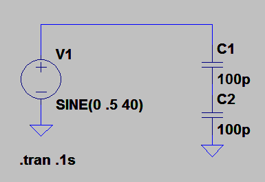
enter image description here

\$\endgroup\$

1 Answer 1

10
\$\begingroup\$

The reason is that a capacitive divider only works for AC. Another way to look at this is that its output impedance is inversely proportional to frequency, so is very high at low frequencies and infinite at DC.

Your combination of small capacitors and low frequency means the outut impedance of this divider will be quite high, about 16 MΩ in your case. That means even a 10x (10 MΩ) scope probe will attenuate the signal significantly. If you changed the capacitors to 100 nF, then the output impedance will be about 16 kΩ and you should see close to half the input sine amplitude on the scope. However, you still won't see 1/2 the DC level since the DC component of the input will always be blocked.

\$\endgroup\$

Your Answer

By clicking “Post Your Answer”, you agree to our terms of service and acknowledge you have read our privacy policy.

Not the answer you're looking for? Browse other questions tagged or ask your own question.