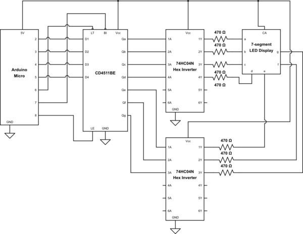
I have designed and built the following 7-segment driving circuit utilising an Arduino Micro in order to try and further understand electronic circuit design:

simulate this circuit – Schematic created using CircuitLab
When turning it on and applying a HIGH voltage to the \$\text{LT}\$ and \$\text{BI}\$ inputs and a LOW voltage to the \$\text{LE}\$ input, regardless of what BCD code I supply to the CD4511BE BCD to 7-segment display driver the LED display just flashes while displaying \$0\$. If I set the \$\text{LE}\$ input to HIGH then the LED display no longer flashes but instead just displays \$0\$.
Here is the test code for the Arduino that I am using:
void setup()
{
  pinMode( 2, OUTPUT );
  pinMode( 3, OUTPUT );
  pinMode( 4, OUTPUT );
  pinMode( 5, OUTPUT );
  pinMode( 6, OUTPUT );
  pinMode( 7, OUTPUT );
  pinMode( 8, OUTPUT );
}

void loop()
{
  digitalWrite( 6, HIGH );
  digitalWrite( 7, HIGH );

  for( int i = 0; i < 10; ++i )
  {
    digitalWrite( 8, LOW );
    digitalWrite( 2, i & 0x0001 != 0 ? HIGH : LOW );
    digitalWrite( 3, i & 0x0002 != 0 ? HIGH : LOW );
    digitalWrite( 4, i & 0x0004 != 0 ? HIGH : LOW );
    digitalWrite( 5, i & 0x0008 != 0 ? HIGH : LOW );
    digitalWrite( 8, HIGH );
    delay( 1000 );
  }
}
Further Information: The following code works as expected:
void setup()
{
  pinMode( 2, OUTPUT );
  pinMode( 3, OUTPUT );
  pinMode( 4, OUTPUT );
  pinMode( 5, OUTPUT );
  pinMode( 6, OUTPUT );
  pinMode( 7, OUTPUT );
  pinMode( 8, OUTPUT );
}

void loop()
{
  digitalWrite( 6, HIGH );
  digitalWrite( 7, HIGH );

  digitalWrite( 2, HIGH );
  digitalWrite( 3, HIGH );
  digitalWrite( 4, LOW );
  digitalWrite( 5, LOW );
  digitalWrite( 8, HIGH );
  delay( 1000 );

  digitalWrite( 8, LOW );
  digitalWrite( 2, HIGH );
  digitalWrite( 3, LOW );
  digitalWrite( 4, HIGH );
  digitalWrite( 5, LOW );
  digitalWrite( 8, HIGH );
  delay( 1000 );
}
