0
\$\begingroup\$

I want to use an Ardiuno to drive a Matrix of TO-220 Mosfets triggering mechanical relays instead of LEDS.

I am making an array of glow-tubes (read: flickery, purple lightbulbs) as a dramatic screen interface for an art installation. I would prefer to use mechanical relays for aesthetic appeal (clickity clack!). I will build a 4*4 prototype, then a 16*16 or larger according to funding etc.

I want it to be an expandable design, so im considering multiplexed control rather than dot matrix.

1: At multiplexing speeds, will a mechanical relay coil hold?

I am switching at full coil voltage, so when multiplexed the current might be alright for holding. Are there any tricks like putting in a capacitor somewhere that might fill up the tiny delay?

2: I will have a diode across the relay coil, but will jamming coils on and off at high rates create any kind of EM noise or current spikes I should be wary of?

3: Am I on the right track? I basically want a controllable lamp array, im using standard LED multiplexing designs because its readily available for arduino so I dont have to code it all aswell :D

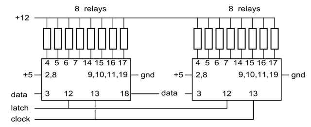
Found an interesting discussion here on a technique using i2c and TPIC6B595 serial latches, i2C and Serial latches
\$\endgroup\$
1
  • 1
    \$\begingroup\$ IMO for this case the benefit of multiplexing is not worth the trouble. You must have the relay, driver, diode, and contacts to whatever the relay is switching anyway. What you can save (1/8 or 1/16 of an IO expander chip) is dwarfed by those fixed 'costs'. Compare to a LED display: there the 'fixed' costs are small (1 LED) compared to the variable costs (driver + resistor), so muxing makes sense. \$\endgroup\$ Commented May 5, 2014 at 7:19

3 Answers 3

1
\$\begingroup\$

Yes, it's doable.

Rather that what you call a "tiny delay" it's the %age on that is a major limiting factor.
For example, a tiny off delay of 100 uS will not allow the relay to operate if the on time is 1 uS.You need to say how many relays you have in mind and what sort of "activity" you have in mind. 1000 or 1000 MOSFETs, all toggling at sub second rates, is quite a different task to say 16 relays which switch at typically 1 per second.

In the latter case above you can use simple multiplexer ICs (such as the CD4051 with a mall capacitor on each MOSFET gate allowing the MOSFET to be used as a sample and hold.

And, if you want impressive and retro 50's methods, you may be able to do the latter task with diodes only, or even just port pins and some resistors and maybe diodes.

So - please better define your need and we can better assist you.


CD4051 sample and hold.

8 relays. 4 port pins. 1 x CD4051.
CD4051 is configured as an 1:8 mux.
3 port pins provide address to 1 of 8 outputs.
Outputs drive FET gates.
Gates have small cap to ground.
CD4051 input is switched high or low by 4th port pin.
If high, selected MOSFET is turned on.
If low, selected MOSFET is turned off.
That is only a 2:1 gain over using 8 x port pins.

16 relays may be drive with 5 lines and 2 x 4051.

Special magic may allow 16 port pins & 2 x 4051 to drive 64 relays.

A capacitor will help but may not be necessary.

\$\endgroup\$
1
\$\begingroup\$

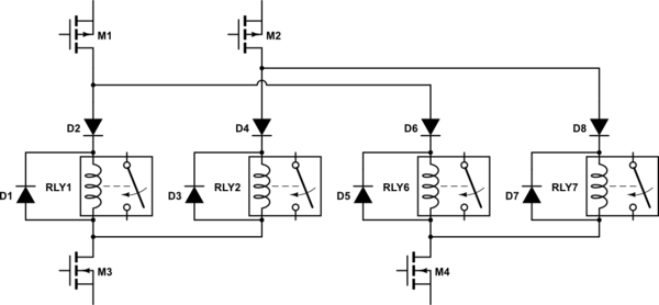
All you need is to keep current through relay above hold threshold. As relay is actualy an inductor, you can feed it with pulses--multiplexing should work. For it you need two diodes for each relay: feed diode and freeweel diode.

schematic

simulate this circuit – Schematic created using CircuitLab

How it works: when both n- and p-MOS switched on relay coil charged with current through feed diode (D2, D4 etc. on schematic). When they're turned off coil wil discarge through its own resistance and freewheel diode, holding some time.

Time it can hold between pulses estimated with formula Thold = R×L×ln(Imax/Ihold), where R and L are coil resistance and inductance, Imax is peak current, and Ihold is holding current.

Note, feed pulses should be enough for current to reach desired level. This may cause need for higher driving voltage.

You'll need to know your relay parameters: switching, holding current, maximum voltage, ohmic resistance and inductance of coil. Using these ones, it is possible to find suitable driving waveform.

\$\endgroup\$
3
  • \$\begingroup\$ Relays have a minimum guaranteed hold in current - lets say this is generated at Kh x Vrated where 0 < Kh < 1. If you are multiplexing the pulses amongst one of N relays so one of N at a time is receiving pulses then Vsupply min to get proper operation is Vrated x N x Kh. Kh may be about 0.5. So for eg 8 relays you need Vrated x 8 x 0.4 = 4 x Vrated. For 16 in a group you need 8 x Vrated. So for 12V relays you'l need > 8 x 12V or 100V+. Not terrible, but worth noting. \$\endgroup\$
    – Russell McMahon
    Commented May 5, 2014 at 8:00
  • \$\begingroup\$ Note that the array shown is a standard X x Y row and column array but drawn differently. \$\endgroup\$
    – Russell McMahon
    Commented May 5, 2014 at 8:01
  • \$\begingroup\$ Standard dual common-cathode schottky diodes can be used for both diodes to reduce part count \$\endgroup\$ Commented Sep 10, 2018 at 19:55
1
\$\begingroup\$

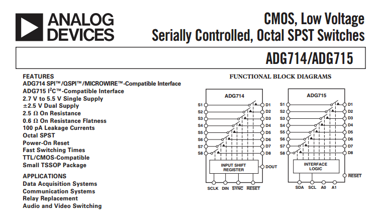
Cutting to the chase, the TPIC6B595 is a decent solution and there's no need to worry about static conditions needing to be "refreshed" to keep the relay coil current high enough to maintain the contact closure. I'd use it (or maybe I'd consider an SPI analogue switch like the ADG714): -

enter image description here

If you were only activating LEDs this would be ideal because you can dispense with the relays. Yeah, I know you want the clickety-clack effect but I thought I'd throw this option in. The 714 version is also cascadable by using the Dout pin connected to the next device's Din pin. Hey you could still use these to drive relays providing the coils were 5V and low power.

\$\endgroup\$

Your Answer

By clicking “Post Your Answer”, you agree to our terms of service and acknowledge you have read our privacy policy.

Not the answer you're looking for? Browse other questions tagged or ask your own question.