2
\$\begingroup\$

I need to design a current limiter for a circuit. I haven't started to design it so I cannot show the schematics, but I'll try to explain it.

It consists just in 2 light sensors. These sensors send a value to an MCU. The supply voltage is 12V but is lowered to 5V for the electronics. The important thing is here:

Depending on the values of the sensors (This corresponds to de programmable part of the MCU) I'll need to have a -1.5V, 0V or 1.5V output value. This is, -1.5V and 1.5V will supply the load, and 0V just won't do anything. The maximum Amperes value must be around 200mA or a bit lower.

So, I ask if you know any component-circuit that could suit this requirements.

UPDATE --

According to the comments, I'll update the post with few more data.

The functionality must be like, if sensor1 < sensor2 then output is -15V, and if sensor1 > sensor2 output 1.5V.

But I still have some things in the air that I need to define:

  • I could use a voltage regulator to low the voltage from 5V to 1.5V, but then, I'll need to define how I generate the negative voltage.
  • I need to set how the MCU tells if the output is negative or positive
  • I need to define the current limiter. I found components like this, but this one has reverse-voltage protection so maybe for this purpose is not the best option
\$\endgroup\$
14
  • \$\begingroup\$ Do I get it right, that you need to limit the absolute value of current on -1.5V to +1.5V rail? \$\endgroup\$
    – Dzarda
    Commented May 6, 2014 at 9:01
  • 2
    \$\begingroup\$ You should try and formulate your exact requirements. If incident light is above X then output is Y. If incident light is below Z then output is -Y etc.. \$\endgroup\$
    – Andy aka
    Commented May 6, 2014 at 9:02
  • 1
    \$\begingroup\$ Add a negative voltage generator and use comparators - get rid of the MCU - it isn't bringing anything to the party as far as I can tell. \$\endgroup\$
    – Andy aka
    Commented May 6, 2014 at 9:53
  • 1
    \$\begingroup\$ What do you need that +/- 1.5V for? There might be an easier way to get the effect you want. \$\endgroup\$ Commented May 6, 2014 at 10:22
  • 1
    \$\begingroup\$ Can you drive your load with full bridge, e. g. +1,5 V on 'negative' load rail, instead of generating negative voltage? This could simplify your task a lot. \$\endgroup\$
    – Vovanium
    Commented May 6, 2014 at 11:45

1 Answer 1

1
\$\begingroup\$

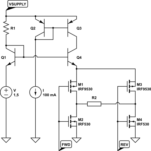
If it suitable your needs, you may use H-bridge to power your load. Here's schematic sketch to give yu idea:

schematic

simulate this circuit – Schematic created using CircuitLab

Here's current limited voltage source (V, I, R1, Q1-Q4) which powers H-bridge of four MOSFETs, and load R2. (Supposed voltage drop across MOSFETS is negligible).

This current limited source consist of current mirror (as current limiter) with emitter follower (as voltage limiter), but you may use any other type you want.

\$\endgroup\$

Your Answer

By clicking “Post Your Answer”, you agree to our terms of service and acknowledge you have read our privacy policy.

Not the answer you're looking for? Browse other questions tagged or ask your own question.