0
\$\begingroup\$

I have a 30Vppk signal (under 1MHz) which terminated to a 50 Ohm resistor. This is the output of the system. It can be optionally terminated by a 50 Ohm load or ** higher ** Z loads.

With 50 Ohm load the system need to push a lot of current. More of what is available from a 20 - 40 mA op amp I'll have in there. What kind of stage should be included to have unity gain without adding almost any distortion or DC offset that will be able to provide 200mA easily (transistor based I guess) ?

I also looked into paralleling op amps but I don't know if this is recommended.

\$\endgroup\$
6
  • \$\begingroup\$ Is it a sinewave and is it 30 p-p or pk? What is maximum frequency and what is the opamp you currently use plus it's gain? \$\endgroup\$
    – Andy aka
    Commented May 9, 2014 at 9:49
  • \$\begingroup\$ @Andyaka - The sine wave is max 30V p-p (Amplitude=15V). Max freq. is around 1MHz. The setup currently being used is ADA4077-1 with gain of 50. I thought maybe a BUF634 could follow to supply more current but I would need some network on the output to introduce some DC to null the pretty large output offset this buffer has. \$\endgroup\$
    – user34920
    Commented May 9, 2014 at 11:07
  • \$\begingroup\$ If you simply add the buffer to the output, but use the buffer output to provide the gain feedback, then the op amp will take care of the offset. However, it's possible that the phase shift of the buffer will make the combination unstable, so you need to be careful. \$\endgroup\$ Commented May 9, 2014 at 12:31
  • \$\begingroup\$ @WhatRoughBeast - This application shows this concept. ti.com/lit/an/sboa065/sboa065.pdf. I assume the cap in the feedback loop is to compesate for the parasitic inductance from the long line? So this should be in the area of 5pF? What about the resistor in the feedback loop and the one from the inverting input to ground? Why is that one needed? \$\endgroup\$
    – user34920
    Commented May 9, 2014 at 14:35
  • \$\begingroup\$ Looking at Figure 1 of your link, pretend that the buffer amp is replaced by a short circuit. What you now have is a non-inverting amplifier, with the gain set by the two resistors, right? The situation does not change when the buffer is added. As for the capacitor, it compensates for the delay added by the buffer, not any line length. As for value, that is hard to say at this stage. Note that the subsequent example did not use such a cap. Try without, and if the parts get hot, add 5-10 pf and see what happens. Note that this will affect the high-frequency response. \$\endgroup\$ Commented May 9, 2014 at 16:57

2 Answers 2

1
\$\begingroup\$

The sine wave is max 30V p-p (Amplitude=15V). Max freq. is around 1MHz. The setup currently being used is ADA4077-1 with gain of 50.

The ADA4077-1 has a gain-bandwidth product of about 4MHz so, with a gain of 50, the bandwidth of the circuit will only be about 80 kHz - this is the first problem to solve - you need an amplifier (before the output driver) with a GBP of at least 50 MHz in order to keep your frequency response level up to 1 MHz.

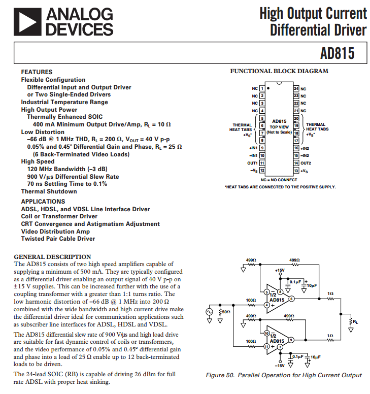
I'd seriously consider looking at something with a GBP of 100 MHz minimum for this. What about the AD815: -

enter image description here

It looks like it can supply the current, can be paralleled, can produce 40Vp-p and has a GBP of 120 MHz. I'd also look at what LT have to offer.

\$\endgroup\$
1
  • \$\begingroup\$ The AD815 is definitely driving a transformer to get to 40Vp-p, I think the datasheet has a few mistakes in it because it doesn't have any way to drive above or below the rails. \$\endgroup\$ Commented Oct 18, 2019 at 14:08
0
\$\begingroup\$

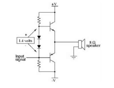
I'm not an expert on this subject. But you could take a look at a class ab power amplifier as used in audio amplification. They are made to deal with very low impedance and high output current to drive speakers.

Something like this: class ab power amp
(source: eet.com)

Although you should probably check whether your transistors can handle your frequencies.

Image reference

\$\endgroup\$

Your Answer

By clicking “Post Your Answer”, you agree to our terms of service and acknowledge you have read our privacy policy.

Not the answer you're looking for? Browse other questions tagged or ask your own question.