1
\$\begingroup\$

I've been trying to simulate the asymmetric pi-attenuator example on this page with different source and load impedances: http://www.electronics-tutorials.ws/attenuators/pi-pad-attenuator.html

I simulated it with an input voltage of 1V. http://postimg.org/image/a25pao46z/

The output I get, however, is 0.41V which corresponds to an attenuation of 7.75dB. Why does this happen?

I also tried simulation the 10dB balanced pi attenuator shown in the page and get near perfect result from it. Would appreciate it if anyone could explain the discrepancy to me.

\$\endgroup\$

3 Answers 3

1
\$\begingroup\$

The pad is giving 6dB of power attenuation. Assuming a source resistance of 75 ohms and 1V open-circuit source voltage, the voltage across the pad input is 0.5V across 75 ohms for a power of

$$p_{in} = \frac{(0.5)^2}{75} = 3.33mW$$

The output voltage is .2047V and this is across 50 ohms so the output power is

$$p_{out} = \frac{(0.2047)^2}{50} = 0.838mW$$

The power is thus attenuated by

$$-10 \cdot \log{\frac{0.838}{3.33}} = 6\mathrm{dB}$$


I also tried simulation the 10dB balanced pi attenuator shown in the page and get near perfect result from it.

If the source and load impedances are equal, the power and voltage attenuation are equal.

$$20 \log \frac{V_{out}}{V_{in}} = 10 \log \frac{V^2_{out}}{V^2_{in}} = 10 \log \frac{V^2_{out}}{Z_{out}}\frac{Z_{in}}{V^2_{in}} = 10 \log \frac{p_{out}}{p_{in}}, \, Z_{out} = Z_{in}$$

If the source and load impedances are unequal, the power and voltage attenuation will not be equal.

$$20 \log \frac{V_{out}}{V_{in}} = 10 \log \frac{p_{out}}{p_{in}} - 10 \log \frac{Z_{in}}{Z_{out}}$$

So, in your example, we should have

$$20 \log \frac{V_{out}}{V_{in}} = -6\mathrm{dB} - 10 \log \frac{75}{50} = -6\mathrm{dB} - -1.76 \mathrm{dB} = -7.76 \mathrm{dB}$$

which agrees with your results.

\$\endgroup\$
2
  • \$\begingroup\$ Thanks so much :) But wasn't the attenuation ratio (k value) calculated for a voltage attenuator? Using the inverse of 20log instead of 10log for a power attenuator. I'm actually required to design a voltage attenuator, so I'm a little confused now \$\endgroup\$ Commented May 25, 2014 at 14:08
  • \$\begingroup\$ @user2802349, take a look at his page: rfcafe.com/references/electrical/attenuators.htm and compare. Even though your reference is using \$K = 10^{6/20}\$, K is then squared in the equation so, in fact, this is the power attenuation, not voltage. \$\endgroup\$ Commented May 25, 2014 at 14:22
1
\$\begingroup\$

The attenuator design process assumes it is driven by a voltage source in series with the design impedance and terminated in the design impedance. In your case, the design impedance is 75 ohms. Although you have properly loaded the attenuator with a 75 ohm resistor, you are driving it with a 1 volt source across the input 75 ohm resistor. This effectively takes the resistor out of the circuit. The 1 volt source should be in series with the 75 ohm resistor to properly simulate the design conditions.

\$\endgroup\$
1
  • \$\begingroup\$ I did try that, but I end up with an output of 200mV which gives me an even worse attenuation of 13.9dB. \$\endgroup\$ Commented May 25, 2014 at 13:10
0
\$\begingroup\$

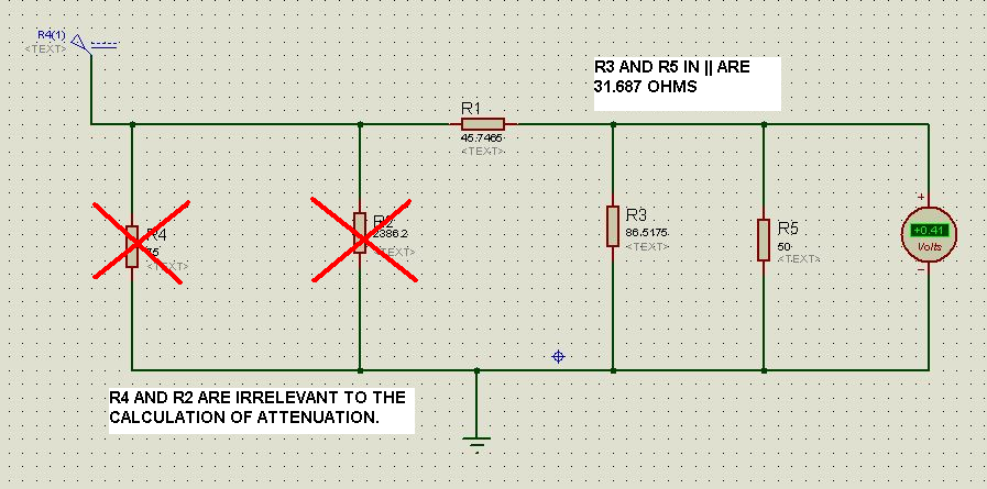
Consider this: -

enter image description here

There are two values that are important here, R1 (45.7465 ohms) and the parallel combination of R3 and R5 (31.687 ohms).

Together they form an attenuator of: -

\$\dfrac{V_{OUT}}{V_{IN}} = \dfrac{31.687}{31.687 + 45.7465}\$ = 0.4092 or -7.761 dB

\$\endgroup\$

Your Answer

By clicking “Post Your Answer”, you agree to our terms of service and acknowledge you have read our privacy policy.

Not the answer you're looking for? Browse other questions tagged or ask your own question.