0
\$\begingroup\$

I have a question in my EC subject like:

Assuming there is a series RC circuit connected to a sinusoidal voltage source with a peak-to-peak value of 8V & frequency of 10kHz and a DC offset of 2V, then what will be the set of values for R and C which only pass the DC voltage to the output & blocks the 10kHz frequency?

I didn't quite get this question. Can anyone help me with it? Thanks in advance!

EDIT

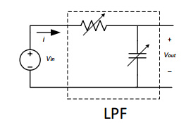
Something like below circuit (as asked by some people)
enter image description here

\$\endgroup\$
7
  • 1
    \$\begingroup\$ What about the question don't you understand? \$\endgroup\$
    – notAlex
    Commented May 28, 2014 at 3:38
  • \$\begingroup\$ I don't know how to calculate those set of values for R and C. I have tried using transfer function, but it doesn't seem to give any clue \$\endgroup\$
    – user23903
    Commented May 28, 2014 at 3:40
  • 1
    \$\begingroup\$ "series RC circuit" means absolutely nothing - I could guess (as others have) but it's better if you produce a circuit diagram. \$\endgroup\$
    – Andy aka
    Commented May 28, 2014 at 7:37
  • 1
    \$\begingroup\$ One more comment: If you really want to "block" on single frequency (10 kHz) you need a low pass with a real zero - however, I suppose that´s NOT what you really need (comlicated circuitry). Normal low pass filter can only attenuate unwanted frequencies but not "block". \$\endgroup\$
    – LvW
    Commented May 28, 2014 at 7:42
  • \$\begingroup\$ Your schematic helps, but it's still unclear what you mean by "blocks the 10kHz". As LvW rightly points out, that kind of filter doesn't block any frequency. It just attenuates them. The 10 kHz will still be there, no matter what components you choose. So how attenuated do you want it to be? \$\endgroup\$ Commented May 30, 2014 at 12:34

2 Answers 2

2
\$\begingroup\$

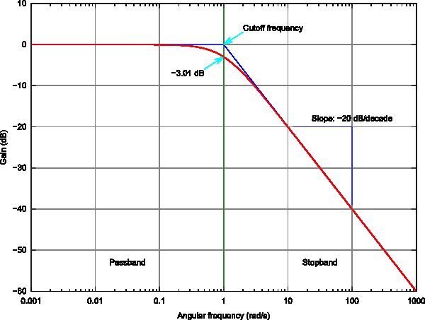
A single stage RC LPF will attenuate according to how far down the slope of the curve. All "1st order" simple filters have a slope which is -6dB per octave (multiple of 2) or -20dB per decade (multiple of 10).

Consider 1% residual noise at 10kHz means -40 dB gain or 40 dB attenuation which is approximately 2 decades below 10kHz or 100Hz. Choosing this breakpoint is a tradeoff between noise suppression and DC response time during power up. However you might choose 60db down from 8V or 8mV which means 3 decades down from 10kHz or 10Hz.

The value of R depends on user requirements for load current and DC drop,which were not given. C is then is computed from f, and R and desired attenuation.

Image

There is no point where there is only DC in theory, as the filter just attenuates, but practical limits can be defined such that the DC response time is not excessively slow. Each application for filtering may be unique.

\$\endgroup\$
0
0
\$\begingroup\$

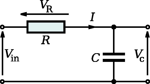
They are looking for a circuit like this (a low pass filter).

Image

Read the Wikipedia article below and look at the "Gain and Phase" equations. Those will help you figure out the values for R and C. Start by picking a common value for C like 0.1uF and a low value for your gain like 0.001 (one thousand times smaller amplitude than your input), then solve for R. Also, ω is in radians per second (10k*2*pi in your case).

RC circuit

\$\endgroup\$
0

Not the answer you're looking for? Browse other questions tagged or ask your own question.