2
\$\begingroup\$

I am looking at using two Cincon (CFM80S240 and CFM60S240) power supplies in parallel to achieve a higher current output. Is this possible? If so, can I just hook them up in parallel, or is there some specific way of doing this to prevent one from "fighting" the other?

Both power supplies are rated for 24V with 1% ripple and noise, +/- 1% voltage accuracy, +/- .5% line regulation, and +/- 1% load regulation.

Ideally, this would be possible since they would both be the same voltage. But, due to tolerances in manufacturing, there is no guarantee that they would be identical voltage outputs.

I wasn't sure if I should also hook up a capacitor in parallel with them to help stabilize the output voltage.

\$\endgroup\$

3 Answers 3

3
\$\begingroup\$

Unless the documentation specifically says this is allowable, you should not parallel supplies (and if it is allowed, be sure to follow all the related recommendations from the manufacturer).

Also, in general, it would not be allowable to parallel two different types of supplies as you have.

You may be able to use ballast resistors to allow paralleling, but they would have to be calculated, would waste power, and would degrade regulation to your load.

\$\endgroup\$
9
  • \$\begingroup\$ Is the main reason due to it being nearly impossible for them to have the same voltage set point? Or is there something else? \$\endgroup\$
    – horta
    Commented Jul 22, 2014 at 15:43
  • 1
    \$\begingroup\$ Yes, they won't be regulating to the same voltage, so one of them will hit a current limit and/or be somewhat overloaded. That could cause a number of problems. \$\endgroup\$ Commented Jul 22, 2014 at 15:44
  • \$\begingroup\$ are you sure the overloading will be a problem even when the power supplies are potentially within .1V of each other? Given the tolerances on both supplies, the maximum and minimum voltages each supply can be is 24.24V and 23.76V, respectively. Given the worst case, this puts the difference at of the two supplies at .48V. One supply is rated for 3.35A and the other is rated for 2.5A. I'd like to pull roughly 5A total from the two in parallel. Do you still think there is an issue here? \$\endgroup\$ Commented Jul 22, 2014 at 16:02
  • \$\begingroup\$ additionally, what if I were to use the CFM80S240 supply in parallel with a voltage supply that I could adjust to the same voltage? I have adjustable power supplies available as well. I was initially starting with the two 24V rated supplies because of "simplicity" \$\endgroup\$ Commented Jul 22, 2014 at 16:04
  • \$\begingroup\$ Yes, I think there could well be an issue. Can I guarantee it will cause problems- no. \$\endgroup\$ Commented Jul 22, 2014 at 16:04
1
\$\begingroup\$

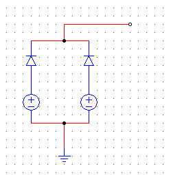
I think you can parallel them by connecting two diodes in series with the supplies like in the following figure, it works almost exactly the same way a rectifier does. The diodes take care of the small offsets in the supplies' voltages and prevent them from shorting. enter image description here

\$\endgroup\$
3
  • 3
    \$\begingroup\$ This is perfectly doable as long as the diodes are rated (and heat sunk) for the current they'll carry. Also, Schottky diodes are preferred, since their forward drop is lower. \$\endgroup\$ Commented Jul 22, 2014 at 18:12
  • \$\begingroup\$ would you not still run into the problem where the voltage at the node connecting the two diodes is not the same? since both diodes have a voltage drop across them thats probably the same, i dont see how you take care of the small offsets. I feel like one diode would still be held below its conducting (knee) voltage and would not even allow current to flow from one of the supplies \$\endgroup\$ Commented Jul 23, 2014 at 15:54
  • \$\begingroup\$ let the sources be V1 and V2 and diodes be D1 and D2 respectively,assume V1 is less than V2,then initially if small current is required, all current would be coming from V2 and D1 would be reverse biased, now if current required by external circuit increases by the capacity of V2 then its voltage would start dropping(typical behavior of most power supplies-due to non zero output resistance),and a point will come when V2 would drop enough to get enough near to the V1 and hence forward biasing the D1 so now V1 will also start supplying the current to meet the requirements. \$\endgroup\$ Commented Jul 23, 2014 at 16:56
0
\$\begingroup\$

I'm not an expert, but you may want to look into 'battery isolator' circuits that are used in charging car batteries with an alternator. There are ways that you can configure your circuit with diodes or something similar so that the voltages don't 'fight'.

\$\endgroup\$
1
  • \$\begingroup\$ Problem with that is that one of them could end up taking most of the current, so it would work for two supplies each of which could supply all the current. It might work by chance because the diodes add ballast drop, but even that is not great because its got a negative tempco (the one that's conducting more gets hotter, so its forward voltage goes down, and it gets more current). Also you lose one diode drop in the output voltage, which might not be acceptable. \$\endgroup\$ Commented Jul 22, 2014 at 15:47

Your Answer

By clicking “Post Your Answer”, you agree to our terms of service and acknowledge you have read our privacy policy.

Not the answer you're looking for? Browse other questions tagged or ask your own question.