2
\$\begingroup\$

I know this sounds like a stupid question, but I'm wondering if the datasheet has an error or something.

I have an ATtiny84 connected to my bench power supply set for 3 volts. It's fused for the internal 8 MHz RC oscillator and a divide-by-8 clock. No watchdog, no brown-out detector.

8 of the I/O pins are hooked to LED anodes, with the cathodes grounded through 0 ohm resistors (yes, the duty cycle is low. Fear not). One of them is connected to a button with the other side grounded. Two of them (shared with MOSI and SCK of the ISP) are not connected (other than to the ISP which is itself disconnected for this test).

setup:

void setup() {

  power_adc_disable();
  power_usi_disable();
  power_timer1_disable();
  ACSR = _BV(ACD);
  set_sleep_mode(SLEEP_MODE_PWR_DOWN);

  pinMode(BUTTON_PIN, INPUT_PULLUP);
  pinMode(UNUSED_1, OUTPUT);
  digitalWrite(UNUSED_1, LOW);
  pinMode(UNUSED_2, OUTPUT);
  digitalWrite(UNUSED_2, LOW);
  for(int i = 0; i < 8; i++) {
    pinMode(LED_PINS[i], OUTPUT);
    digitalWrite(LED_PINS[i], LOW);
  }
  while(1) sleep_mode();
}

The result is 240 µA of current draw. This is measured with a µCurrent Gold, so I have some confidence in the accuracy.

The datasheet (figure 21-1) says that powered down at 25°C the chip should take more like 100 nA.

WTF?

For reference, here's the actual sleep function used by the code (but not part of this test):

void sleepNow() {
  // All LEDs off
  for(int i = 0; i < 8; i++) {
    digitalWrite(LED_PINS[i], LOW);
  }
  cli();
  power_timer0_disable();
  PCMSK0 |= _BV(PCINT5);
  GIMSK |= _BV(PCIE0);
  sleep_enable();
  sei();
  sleep_cpu();
  sleep_disable();
  PCMSK0 &= 0xff ^ _BV(PCINT5);
  GIMSK &= 0xff ^ _BV(PCIE0);
  power_timer0_enable();
  button_debounce_time = millis();
  ignoring_button = 1;
  place_in_pattern = -1;
  milli_of_next_act = 0;
}

It yields the same current consumption, which is why I reduced this test down to just putting the chip to sleep in as little code as possible.

The schematic:
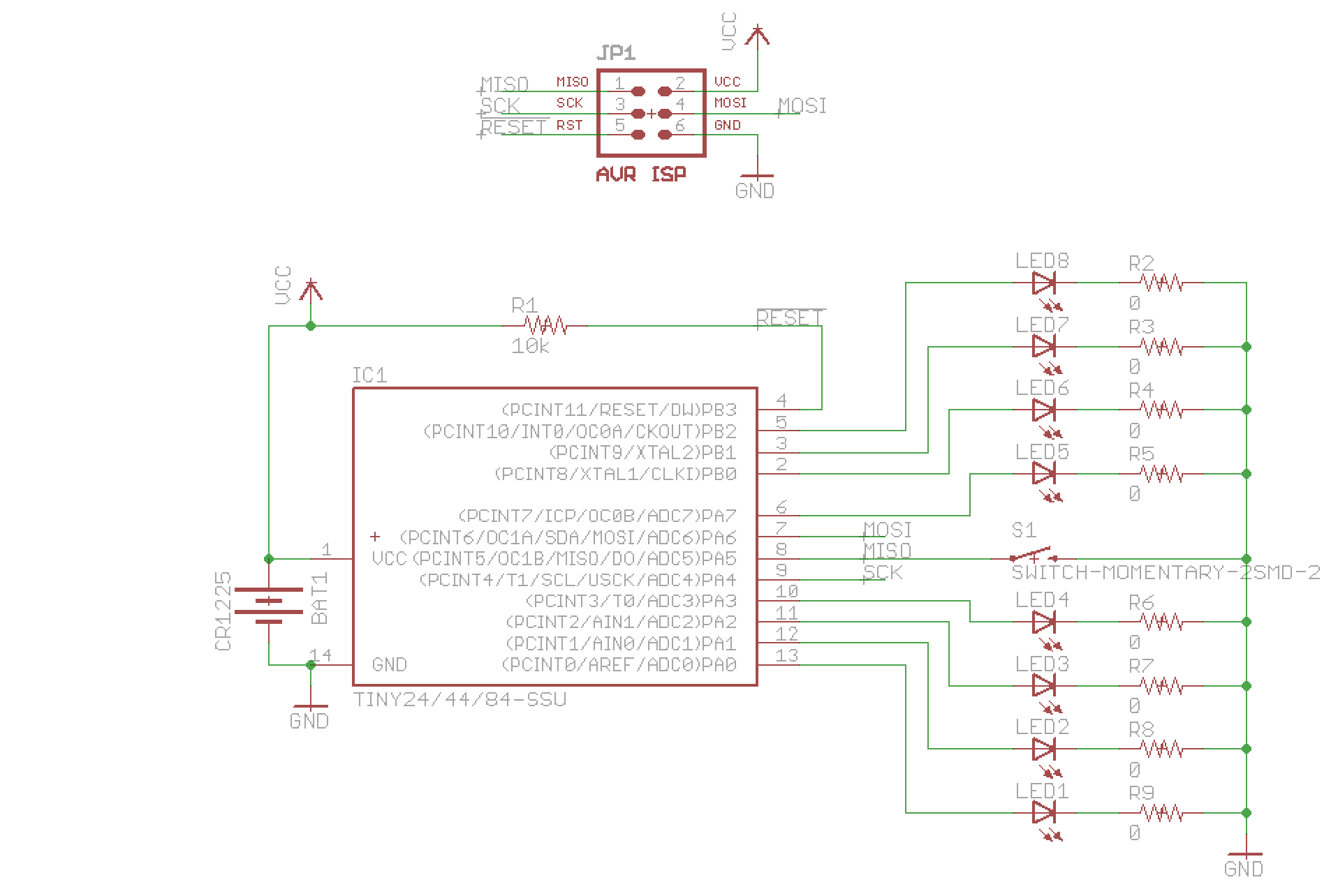
enter image description here

For this test, the battery is absent and 3.00 volts is being fed in to the Vcc and GND pins of the ISP header. No other ISP pins are connected.

I've repeated this experiment with an ATTiny85 on a breadboard. I programmed it with this:

#include <avr/sleep.h>
#include <avr/power.h>

void setup() {
  PRR = 0xff;
  set_sleep_mode(SLEEP_MODE_PWR_DOWN);

  pinMode(0, OUTPUT);
  digitalWrite(0, LOW);
  pinMode(1, OUTPUT);
  digitalWrite(1, LOW);
  pinMode(2, OUTPUT);
  digitalWrite(2, LOW);
  pinMode(3, OUTPUT);
  digitalWrite(3, LOW);
  pinMode(4, OUTPUT);
  digitalWrite(4, LOW);
  while(1) { sleep_mode(); digitalWrite(2, HIGH); }
}

void loop() {}

I then fused it for a 1 MHz internal clock, and then disconnected everything but power and ground. The result: 240 µA.

Now, all of this would be explained if the graph in figure 22-11 (this is the ATTiny85 datasheet now) had the axis mislabeled and was actually in mA rather than µA. The power down current vs Vcc and temperature that I'm using lines right up with the graph 3 orders of magnitude higher.

Has anyone gotten an ATTiny to draw less than a micro-amp (other than just disconnecting power)? Can someone write a sketch that will make an ATTiny do nothing but just go permanently to sleep consuming as little power as possible with nothing connected except power and ground? That's what I've been trying to do, and there clearly is something that I'm missing and I'll be damned if I can figure out what it is.

\$\endgroup\$
7
  • \$\begingroup\$ For completeness, do you have a voltage regulator in the circuit? It's quiescent current might be that big. I assume the datasheet has not got an error that big. It is quite an old chip, so I would expect an errata to have fixed the datasheet by now. \$\endgroup\$
    – gbulmer
    Commented Aug 23, 2014 at 18:04
  • \$\begingroup\$ No. I am using a bench supply set to 3.00 volts going directly to Vcc. \$\endgroup\$
    – nsayer
    Commented Aug 23, 2014 at 18:42
  • \$\begingroup\$ Oh, and the µCurrent is on the low side, so that there's a common ground with the scope being used to measure the voltage (which is what the µCurrent outputs). \$\endgroup\$
    – nsayer
    Commented Aug 23, 2014 at 19:23
  • \$\begingroup\$ Okay - so the only parts current can flow through are the ATTiny and the closed switch? 240uA looks so big, that it might be more than one cause. To reduce the number of possibilities, is it practical to disconnect all I/O pins except the switch? \$\endgroup\$
    – gbulmer
    Commented Aug 23, 2014 at 19:25
  • \$\begingroup\$ The only thing hooked up to the pins are LEDs, and the pins are all set LOW - there should be no current flowing at all through them. The only part that has both +3 and ground hooked up is the ATTiny (assuming the button is not being pushed - which it isn't). \$\endgroup\$
    – nsayer
    Commented Aug 23, 2014 at 21:42

3 Answers 3

3
\$\begingroup\$

This comment on reddit pointed me to this page, which says that clearing the ADEN bit in ADCSRA shed as many µA as are currently in excess in my test rigs. I am away from the lab right now, but when I get home tonight, that's the first thing I'll try. I'm optimistic. I do know that the ADEN bit gets set in init() in wiring.c...

If it's confirmed, then the lesson is that PRR is not enough to turn the ADC all the way off.

EDIT: It is confirmed. The one added caveat is that order matters. ADCSRA must be written before PRR.

My sleep_tiny_sleep sketch (last above) now takes < 100 nA.

\$\endgroup\$
1
\$\begingroup\$

Are you certain sleep_mode() is able to put everything into that 100nA power down mode?

A simple explanation is it does not go that deep.

says

As the sleep_mode() macro might cause race conditions in some situations, the individual steps of manipulating the sleep enable (SE) bit, and actually issuing the SLEEP instruction, are provided in the macros sleep_enable(), sleep_disable(), and sleep_cpu()much .

So they advise against using sleep_mode()

Even if sleep_mode() returns with an error, it is in a while(1) so it might just be going round and round.

Maybe change while(1) sleep_mode(); into something like

while(1) {
    sleep_mode();
    blink LED
}

and see if the LED is on. If you have an oscilloscope, have a look at the pin, and see what is happening.

Edit:
One approach would be to look at the ATTiny84 datasheet, and see which peripheral might be consuming that much current.

240µA is so big, it may be more than one cause; no single peripheral on the data sheet looks big enough to consume that much.

The internal I/O pin pull-up resitors could leak enough to reach that order of magnitude, so try to ensure they are all off.

\$\endgroup\$
13
  • \$\begingroup\$ I'll try it. sleep_mode() is part of the AVR power.h api: nongnu.org/avr-libc/user-manual/group__avr__sleep.html I'd be a little surprised if it didn't do what it says it's supposed to. \$\endgroup\$
    – nsayer
    Commented Aug 23, 2014 at 17:50
  • \$\begingroup\$ I agree. However it clearly isn't working!-) Actually I don't hold out much hope that it checks enough to find out what is wrong. But you might find a clue. \$\endgroup\$
    – gbulmer
    Commented Aug 23, 2014 at 17:53
  • \$\begingroup\$ The light never lights up. \$\endgroup\$
    – nsayer
    Commented Aug 23, 2014 at 17:57
  • \$\begingroup\$ Oh! The nongnu.org/avr-libc/user-manual/group__avr__sleep.html page does recommend a different way to sleep, and identifies problems with using other ways. user34920 diagnosis is likely correct. \$\endgroup\$
    – gbulmer
    Commented Aug 23, 2014 at 17:58
  • 2
    \$\begingroup\$ The pull-up or pull-down resistor on the button will add some extra current flow. \$\endgroup\$
    – gbulmer
    Commented Aug 23, 2014 at 18:00
0
\$\begingroup\$

This does not look like the proper sleep sequence to me...

  1. Set the sleep mode
  2. disable global interrupts
  3. condition to sleep (if...)
  4. enable sleep
  5. enable global interrupts
  6. sleep cpu
  7. disable sleep (this executed after external interrupt)

Try this and report back.

\$\endgroup\$
3
  • \$\begingroup\$ That's the sequence used for the actual code - which uses the button to wake up. But this is just a test. I am trying to put the chip into permanent sleep just for now, and that doesn't seem to be working as expected. \$\endgroup\$
    – nsayer
    Commented Aug 23, 2014 at 17:53
  • \$\begingroup\$ Try using this sequence without other code in the middle, make sure you follow all the steps in the right order. give it a go it will take you 2 minutes. \$\endgroup\$
    – user34920
    Commented Aug 23, 2014 at 17:54
  • \$\begingroup\$ The original sleep code - which I pasted above - yields the same current consumption. I reduced the code down to the minimal case for this question to try and reduce the scope. \$\endgroup\$
    – nsayer
    Commented Aug 23, 2014 at 19:02

Your Answer

By clicking “Post Your Answer”, you agree to our terms of service and acknowledge you have read our privacy policy.

Not the answer you're looking for? Browse other questions tagged or ask your own question.