10
\$\begingroup\$

while 555 contest is long gone, I am still debugging my device, where I already abandoned 555 itself :-)

At the moment, I am driving PC fan from an PWM (30kHz) signal from atmel uC.

I am powering P-MOSFET with a simple 1-BJT-transistor-"driver". Output is filtered with an 22uH inductor + 330uF cap. Surely I have kickback diode in place.

The problem I have is while I have 256 "levels" of PWM, I am getting most of output difference somewhere in the 1-20 range. It looks like even short pulses have the "power" to drive the fan at full power.

1) How can I make it "less" powerful? Will I have more powerful fans underpowered then?

2) On the drain of the mosfet I see some 1-3Mhz ringing with some 5V amplitude, and while it all works, I don't like it (no ringing on the source or gate). What causes it and how should I fight it?

Update: R1 - 1kOhm R2 - 47Ohm MOSFET - is PMOSFET from motherboard Diode is some medium-size Schottky one, with 0.2V drop.
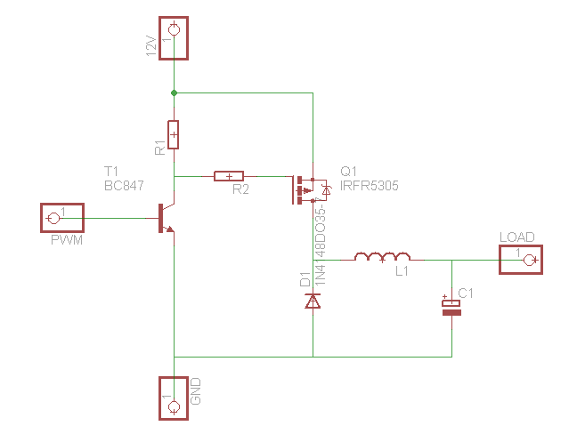
enter image description here

\$\endgroup\$
0

5 Answers 5

10
+100
\$\begingroup\$

I think you're being bitten by the physics of the fan.

The power in a stream of moving air is proportional to the cube of the air velocity, and the rotational speed of a fixed pitch propeller (i.e., fan) is directly proportional to the air speed. This means that to double the air speed from your fan (or its rotation rate), you have to put in eight times as much power. Or conversely, to cut speed in half, you only need an eighth of the power. If you call the air speed you get at 100% duty cycle 'full speed', then 'half speed' will occur at 1/8th the power level; at 12.5% duty cycle. Even more dramatically, quarter speed would be at 1/8th of that, at just 1.5625% duty cycle. In other words, whatever speed you get at the very lowest duty cycles is nearly all you're going to get, because power in moving air is so non-linear.

\$\endgroup\$
1
\$\begingroup\$

Edited based on the schematic:

You essentially have a buck converter there. The P-channel is sort of acting like the high-side N-channel that you usually have in a buck. I doubt that the FET is turning on as solidly as a N-channel with high-side drive would, but it still is acting buck-ish.

If you don't have good speed control, you probably have a fan that only operates over a limited DC input range (10-12V), or the high-side P-channel is dissipating some of the input voltage, limiting the maximum DC that the fan can see.

Or, rearrange the buck so the FET is in the low side and use a N-channel there.

If you have HF ringing on the MOSFET, you can try to slow down the switching by increasing the series gate resistance, or add a high-frequency RC snubber circuit across the gate-source to suppress the rings.

\$\endgroup\$
1
  • \$\begingroup\$ No power dissipation on mosfet, it opens fully. I can't use low-side N-MOSFET as I need to sense rotation speed. I have some ringing but it's not my main problem at the moment. \$\endgroup\$ Commented Apr 29, 2011 at 22:36
1
\$\begingroup\$

A while back I did a similar circuit, basically a PWM with an LC filter on the output. This is, in essence, a switching buck DC/DC converter. I'll cut to the chase: It didn't work.

The main problem is that the cap was completely charging when the PWM was on and not fully discharging when the PWM was off-- thus basically powering the fan 100% of the time. Also, keep in mind that most 12v fans will spin when powered off of only 4v.

My suggestion is to remove the LC filter and see if that improves things (it should). If you're not trying to pass FCC tests then you're done. If you are trying to pass tests, then simply adding a small cap (1 uF or less) should work. Other than EMI emissions, there isn't much reason to filter things to a fan.

Alternatively, if you leave the LC filter in there then what you're really doing is not PWMing the fan, but controlling the speed by varying the voltage. For this to work, you should either increase the size of the inductor and/or increase the PWM frequency. Basically, you want to make this switching buck DC/DC converter work properly.

\$\endgroup\$
3
  • \$\begingroup\$ My soul does not allow me to leave that unfiltered. Also, I "sings" then :-) It will work in my case, is uC will be able to work even in 1-20 range, just need to change PWM value too often... \$\endgroup\$ Commented Apr 11, 2011 at 15:24
  • \$\begingroup\$ @BarsMonster I'm not sure what you mean by "I 'sings' then". If you mean to say, "the fan makes a note" then the simple answer is to change the PWM frequency so it no longer does that. Also, I edited my answer above to cover the case were you just have to keep the LC filter. \$\endgroup\$
    – user3624
    Commented Apr 11, 2011 at 15:59
  • \$\begingroup\$ Yes, varying voltage is what I am trying to achieve. I know it should not sing at 30kHz, but for some reason, it does a little without filtering. Increasing clock might be problematic as I would need to add an external clock (this is attiny13, only 8Mhz is available on internal RC, and no way to attach crystal) \$\endgroup\$ Commented Apr 11, 2011 at 16:33
0
\$\begingroup\$

Varying PWM duty-cycle in an attempt to gain linear (or near-linear) voltage output works when you're smoothing charge and discharge from an "output" which sources and sinks current at the same rate. Typically, you would see this with a bipolar (by this I mean both polarity, not BJT) output feeding a R/C filter.

What you've built, instead, is a variable-duty cycle charge injection circuit (a sort of buck converter) -- you're not controlling voltage because the discharge rate of your filter is controlled by the load, not the PWM circuit. You're operating at an open loop here - and so beyond a small window, you'll either not have enough current and the voltage goes to zero, or you'll have too much current and you get full voltage.

I suppose one quick hack to get the result you want is to have a FET totem-pole that would pull the left side of L1 to ground. I'm not sure your 12V power supply is going to thank you for that, though.

\$\endgroup\$
1
  • \$\begingroup\$ I had a feeling that with big enough cap I should get any voltage between 0 and 12, and with 10'000uF I kinda get that. The only problem is that PWM->Voltage graph is very very nonlinear, so it's hard to control below 10V. That's the question - how to make 'rampup' slower let's say on 50% duty cycle. \$\endgroup\$ Commented May 2, 2011 at 2:10
0
\$\begingroup\$

"Bitten by the physics of the fan" sounds likely.

You could recalculate your scale according to the inverse square law p/4πr^2. But you will need more than 8 bit of PWM resolution to make that work.

\$\endgroup\$

Your Answer

By clicking “Post Your Answer”, you agree to our terms of service and acknowledge you have read our privacy policy.

Not the answer you're looking for? Browse other questions tagged or ask your own question.