1
\$\begingroup\$

I'm kind of a noob when it comes to electronics (I'm mainly a computer programmer), so please bear with me. I want to construct a one shot non-retriggerable pulse generation circuit that has two trigger inputs. The inputs on the triggers are going to be persistent signals (not just pulses) so I would like the circuit to only generate a pulse when one of the input lines is pulled high, and not generate another one until either the second input line also gets pulled high, or the first input gets pulled low and then high again (this behavior may be easier to achieve by using two pulse generators and tying the outputs together, but in this case it is still important that each pulse generator only fire a pulse when the trigger signal goes from low to high, and not continue to generate pulses if the signal then remains high for a while).

The reason the trigger signal may remain high for a while is because the triggers are going to be user-operated. For example, let's say that each trigger is connected to a button, and the output is connected to an LED (just an example, not what I actually intend to use this circuit for). If the user presses either button, the LED should flash once, regardless of whether the user continues to hold down the button after pressing it. If the user then presses the second button while still holding down the first one, the light should flash a second time; the light should not flash again until the user releases at least one of the buttons and then presses it down again.

I hope I'm making myself clear as to what I need this circuit to do. As I said before, I am mainly a computer programmer, so I will provide some pseudo-code below if it helps to understand what I am asking.

IF (trig1.prevState = 0 AND trig1.currentState = 1) OR (trig2.prevState = 0 AND trig2.currentState = 1) THEN 
output.currentState <- 1
ELSE 
output.currentState <- 0
ENDIF

I am not against using a microcontroller, but only if the delay it introduces is negligible (I need the pulse to occur nearly the instant the trigger line is pulled high).

As I said, I'm kind of a noob, so I would really appreciate it if someone could provide a full schematic of the best way to build this circuit, although any suggestions at all are still welcome. I don't want this to be too expensive, so no super expensive parts please.

\$\endgroup\$
5
  • \$\begingroup\$ I think your question would be much better if you asked for advise on a schematic you designed or found. Asking for someone to "provide a full schematic" here is not proper. StackExchange answers questions, not fulfills engineering requests. \$\endgroup\$
    – JYelton
    Commented Oct 15, 2014 at 2:51
  • \$\begingroup\$ Sorry, if i had any experience at all i would have asked for advice. I have only tried working with circuitry on 2 occasions, both of which i could never get working right. What i do not want are answers along the lines of "Use a 555 timer and an RC circuit". I know what both of these things are, but i have no idea how they work or how to implement them. I asked for an exact answer because i figure that people here actually know what they are doing, where as i would probably end up soldering the capacitor to the wrong pin on the 555. \$\endgroup\$
    – android927
    Commented Oct 15, 2014 at 4:38
  • \$\begingroup\$ Also, most of the time i've spent on StackExchange has been on StackOverflow and SuperUser, where it is not uncommon to receive an exact answer to your question. \$\endgroup\$
    – android927
    Commented Oct 15, 2014 at 4:40
  • 4
    \$\begingroup\$ All I am saying is that asking for a circuit here is akin to asking for "the code" on Stack Overflow. \$\endgroup\$
    – JYelton
    Commented Oct 15, 2014 at 4:42
  • \$\begingroup\$ Okay, i edited the OP slightly. I hope you find it more acceptable now. \$\endgroup\$
    – android927
    Commented Oct 15, 2014 at 5:17

3 Answers 3

2
\$\begingroup\$

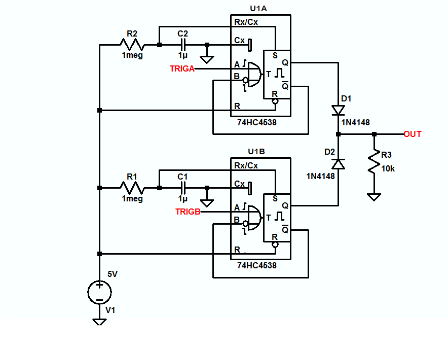
Here's a really cheap, simple way to do it in hardware; no code, no debounce, no input-to-output delay, it just works.

TRIGA is one high-going input, TRIGB is the other, and OUT is, well, the output.

enter image description here

\$\endgroup\$
9
  • \$\begingroup\$ Just to clarify, you are sure that a pulse will only fire if the trigger signal goes from low to high, and will not continue to fire in the event that the trigger remains high for several seconds afterward? Also, is this design non-retriggerable, and if so what is the time delay before it can be re-triggered? \$\endgroup\$
    – android927
    Commented Oct 16, 2014 at 22:47
  • \$\begingroup\$ I intend to use this circuit to wire 2 electronic bass drum pedals to an electronic drum kit that only accepts one input line for the bass drum (in a manner such that the pedals will behave similarly to an actual double bass drum pedal), so the delay needs to be as short as possible. \$\endgroup\$
    – android927
    Commented Oct 16, 2014 at 22:58
  • \$\begingroup\$ @android927 1. Here's a link to the 4538 so you can check it out for yourself. 2. Kinda late to be asking, but how about some links to the equipment you're talking about? \$\endgroup\$
    – EM Fields
    Commented Oct 17, 2014 at 13:10
  • \$\begingroup\$ Well, this may sound silly, but because i live in a tiny college apartment that won't fit my actual drum kit, i picked up a cheap toy drum kit that uses capacitive touch sensors (which actually works quite well, i might add) so that i could still lay down some beats during the school year. The foot pedal connects via a standard 3.5mm stereo jack, and an additional pedal for a hi-hat can be plugged into a second jack on the first pedal (although daisy chaining more than 2 is not allowed). \$\endgroup\$
    – android927
    Commented Oct 18, 2014 at 1:07
  • \$\begingroup\$ Since the pedals are unpowered, my theory is that a signal is put on one of the 3 lines, and the device listens for a return signal on the other 2 lines, with the pedals themselves basically acting as switches. I assume that one of the 2 return lines comes straight from the connected pedal, while the other is patched through from the second pedal via the first pedal's jack (but this is all just a hypothesis). The issue is that when i try to get double bass by connecting 2 pedals via a splitter, each pedal will only work if the other pedal is not being pressed (this i have actually tested). \$\endgroup\$
    – android927
    Commented Oct 18, 2014 at 1:25
2
\$\begingroup\$

A PIC 10F200 can do this job easily. Since this is working on a human time scale, the microcontroller will react instantaneously. Humans don't notice a delay up to a few ms or low 10s of ms, so the PIC 10F200 running at 1 MIPS is plenty fast enough to poll the two inputs, decide what to do, and light or unlight the LEDs accordingly. Even if it took 100 instruction cycles to react (that's a lot), the delay would only be 100 µs. Nobody will ever notice that delay.

Another thing you should be aware of is that switches bounce. You need to add deliberate debouncing code so that the "chatter" when the switch closes and opens doesn't get interpreted as a lot of fast button presses. This is normal and common thing to do with mechanical switch signals. Look up "switch debouncing" for more information.

\$\endgroup\$
0
\$\begingroup\$

Buy the cheapest microcontroller you can find, and implement the code you just presented. If you're super worried about delays then use interrupts to react to the button presses. I doubt the microcontroller would be too slow even with just polling since it won't be doing anything else.

\$\endgroup\$
5
  • \$\begingroup\$ What micro controller would you recommend? Remember, i have literally NO experience beyond some basic breadboarding, soldering, and watching Ben Heck on youtube. \$\endgroup\$
    – android927
    Commented Oct 15, 2014 at 5:20
  • \$\begingroup\$ @android927 Atmel is very well received in the hobbyist community, probably due to it’s widespread use in Arduinos. Any ATtiny would do, if you wire your triggers to the two external interrupt pins (before buying, make sure that your tiny model has in fact two ExtInts). If you don’t have programmer hardware and/or no μC experience, and no arduino you could abuse as a programmer, you should probably go for an Arduino (these have larger atmel chips, so you can do the same thing with these). \$\endgroup\$ Commented Oct 15, 2014 at 5:26
  • \$\begingroup\$ I don't have any prior μC experience so i will probably go for the Arduino. Will the Arduino Uno fulfill my purpose? \$\endgroup\$
    – android927
    Commented Oct 15, 2014 at 5:55
  • \$\begingroup\$ Actually, i think i might get one of these and go with an ATtiny. Would you recommend the ATtiny45 or the ATtiny85? \$\endgroup\$
    – android927
    Commented Oct 15, 2014 at 6:25
  • \$\begingroup\$ @android927 Pick the cheaper one. The only difference between ATtiny45 and 85 is flash memory, with 85 being the larger one. Often 85 is cheaper when buying them from a local webshop or so. Beware to order PDIP8 package, not SOIC8 if you want to use the linked programmer. \$\endgroup\$
    – jippie
    Commented Oct 15, 2014 at 19:11

Your Answer

By clicking “Post Your Answer”, you agree to our terms of service and acknowledge you have read our privacy policy.

Not the answer you're looking for? Browse other questions tagged or ask your own question.