2
\$\begingroup\$

I know recent motherboards already provide these, but lately USB ports are also available in many different gizmos (smartphone chargers, TVs, standalone players, etc.), which I am often tempted to use as a power sources for USB toys, mini PCs, etc.

So I am looking for a solution to dynamically limit the output current so both the USB host and the guest won't take any damage due to overcurrent. Under/overvoltage protection is also needed for the same purpose.

I prefer an easy solution (based on an IC?) that i can connect like an USB extension cable to "unsafe" power-hungry toys.

EDIT: i'd like a solution with an user-selectable upper current limit. My ideal range would be 0.1-2.5A. According to the ICs i've found this range is too wide, so maybe i will build 2 different limiters for 2 different ranges (unless you know some trick to extend the range).

\$\endgroup\$
2
  • \$\begingroup\$ It seems like the MAX1607 is able to pass through the input voltage and has internal circuitry similar to what my answer contains, with a MOSFET of ~100mOhm on resistance. The current limit is perhaps too high, and will break most USB output ports. \$\endgroup\$
    – KyranF
    Commented Oct 22, 2014 at 11:45
  • \$\begingroup\$ This can be directly applicable ti.com/product/tpd4s214. Generally USB Power switch category of devices will give OC/UV facilities as per USB standard. like Micrel's MIC2025-1, or TI's TPS202x etc....we need to add Over Voltage protection at the output using discretes. something like this......maximintegrated.com/en/app-notes/index.mvp/id/760 or simple 'eetimes.com/author.asp?section_id=183&doc_id=1279006' \$\endgroup\$
    – user19579
    Commented Oct 22, 2014 at 15:31

1 Answer 1

1
\$\begingroup\$

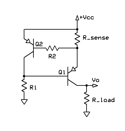
I would make a little in-line device with a 500mA resettable PTC fuse, and you can make an active high side current limiting circuit with MOSFET, low Ohm sense resistor, opamp, and transistor or two. The general circuit looks like this (source Wikipedia Current limiter page):

current limiter circuit high side

The description of the image contains the method of operation: Electronic circuit schematic for a current limiter or current source. An issue with the circuit, is that Q1 will not be saturated unless its base is biased about 0.5 volts above Vcc. This circuit operates more efficiently from a single (Vcc) supply. In this circuit, R1 allows Q1 to turn on and pass voltage and current to the load. When the current through R_sense exceeds the design limit, Q2 begins to turn on, which in turn begins to turn off Q1, thus limiting the load current. The optional component R2 protects Q2 in the event of a short-circuited load. When Vcc is at least a few volts, a MOSFET can be used for Q1 for lower dropout-voltage. Due to its simplicity, this circuit is sometimes used as a current source for high-power LEDs.

The key part to notice, and which you will have to do with only 5V+-10% from a USB supply, is to use a MOSFET to reduce the voltage drop while in 'normal' operation, and to use a very small R_sense so it does not affect the circuit, and then amplify the differential voltage using an Op-amp. A general purpose op-amp with a gain of 10 for example, will allow you to make R_sense 10 times smaller than what would be needed in the shown circuit for the desired current limit.

EDIT: Of course a cheap and simple IC like the Richtek RT9706 from places like Digikey will work, some have fixed current limits and some you can adjust them.

\$\endgroup\$
0

Your Answer

By clicking “Post Your Answer”, you agree to our terms of service and acknowledge you have read our privacy policy.

Not the answer you're looking for? Browse other questions tagged or ask your own question.