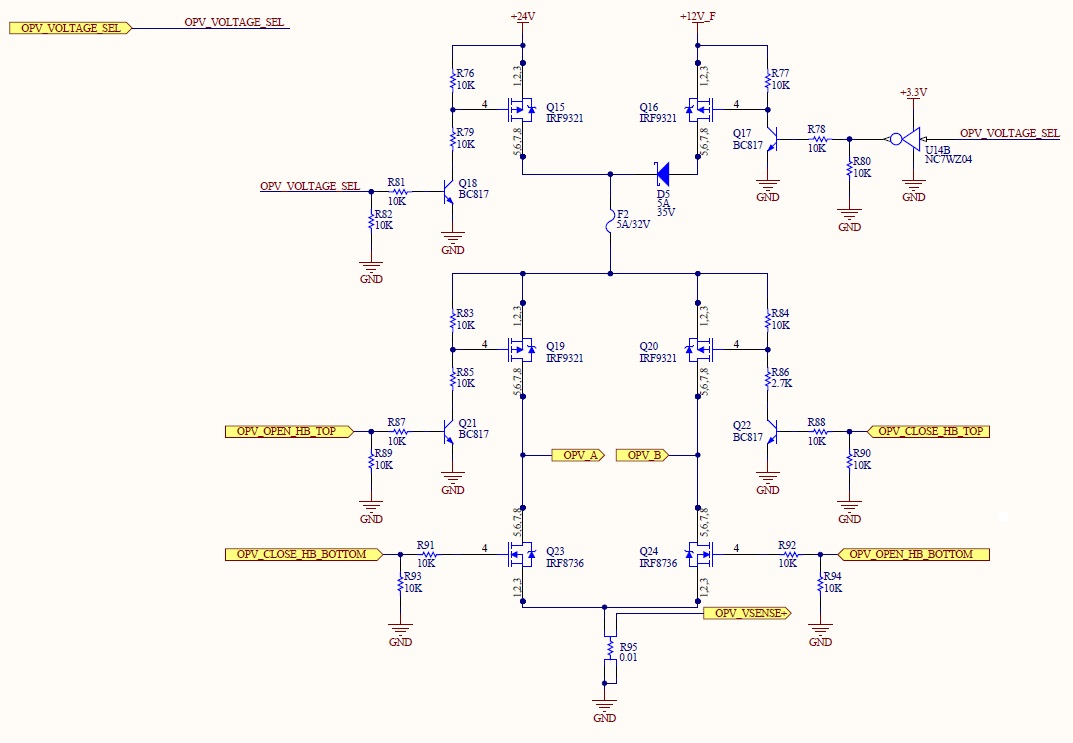
In my design two solenoids (MagLatch C5-L-272-B-1 and MagLatch B22M-L-154-M-36) are used. Each solenoid is driven by a H bridge powered by a voltage selector (12V or 24V). The command signals are driven by a microcontroller.

The 24V is used to latch (OPV_CLOSE_HB_TOP and OPV_CLOSE_HB_BOTOM activated) the solenoid in one position and 12V (OPV_OPEN_HB_TOP and OPV_OPEN_HB_BOTOM) is used to unlatch it. The reason why there is a voltage switch is to follow the datasheet (Link) remark:
The reverse voltage applied is dependent on the load attached to the plunger but must be well below the initial energizing value.
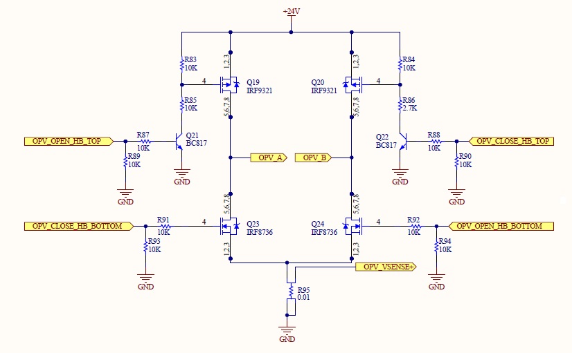
So to latch the solenoid a pulse of 24V is applied for 20 ms and to unlatch 12V for 20 ms is applied. This works perfectly, but I am trying to improve this design by removing the 12V power supply and use only 24V for the H bridge, as shown on the next figure:

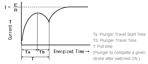
To latch the solenoid the same pulse is applied (24V for 20 ms), but now to unlatch the solenoid a pulse of 24V for a smaller duration (10 ms) is applied. By doing this the energy provided to unlatch the solenoid is half of energy provided to latch. For me the new design is equivalent to the old one. Am I right?
I have tried the new design and it seems to work, but I would like to know if it can destroy the solenoids in the future or if other unwanted behaviour can occur.
Any others suggestions or warning are welcome.
Thank you.

